Earlier this year, I had the privilege of working on a research project at NASA’s Langley Research Centre. Apart from interacting with world-renowned scientists and engineers, what impressed me most was the mind-blowing heritage of the site.
NASA Langley is the birthplace of large-scale, government-funded aeronautical research in the US. It was home to research on WWII planes, supersonic aircraft, the lunar landers and the Space Shuttle. Who knows how the Space Race would have panned out without the engineers at NASA Langley?
Today, Langley is at the helm of leading aeronautical engineering into the 21st century with technologies such as advanced composites, alternative jet fuels and the journey to Mars.
NASA Langley was established in 1917 as NACA’s (short for National Advisory Committee for Aeronautics and renamed to NASA in 1958) first field centre and is named after the Wright brothers rival Samuel Pierpont Langley, who’s Aerodrome flyer twice failed to cross the Potomac river in 1903.
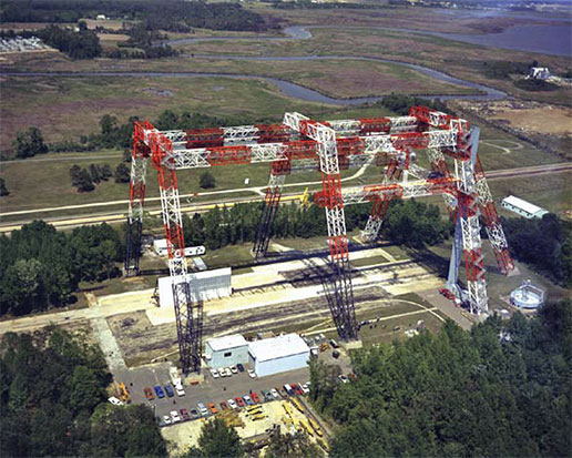
Amid the new composites facilities I was working on are strewn old gems such as NACA wind-tunnels from the 1920s and 1930s, and the massive “Lunar Landing Research Facility”, or simply “The Gantry”, used to test the Apollo lunar landings in the 1960’s. During Project Mercury NASA Langley was the home of the Space Task Group, a team of engineers spearheading NASA’s first human spaceflight between 1958 and 1963. The gantry has since been re-purposed for land-based crash landings, such as on the Orion spacecraft.
Another historic site is the Aircraft Landing Dynamics Facility (ALDF), a train carriage that could be accelerated by 20Gs up to 230 mph by a water-jet spewing out the rear, and used to test impact on landing gears and airfield surfaces. The facility has provided NASA and its partners and invaluable capability to test tires, landing gear and understand the mechanism of runway friction. Prior to WWII many engineers were convinced that the abundance of rivers and sea water would mean that the aircraft would land primarily on water. As a result research on the mechanics of landing on terra firma was lagging behind and post WWII almost a third of all aircraft accidents could be attributed to landing issues [2]. Throughout its 52 years of operation the ALDF has saved thousands of lives by making aircraft safer.As the centre’s original aim was to explore the field of aeronautics, specifically aerodynamics and propulsion, the world’s largest wind tunnel was constructed at Langley in 1934. At the time the Full-Scale Wind Tunnel was one of the first to fit an entire full-scale aircraft with a whopping 30 by 60 foot cross-section. The tunnel’s 4000 bhp electric motors (4000 bhp !!) accelerated the airflow to 118 mph (181 km/hr) and was used to test basically every WWII aircraft prototype. After the war, both the F-16 and the Space Shuttle were tested in the Full-Scale Wind Tunnel. Even though it was declared a National Historic Landmark in 1985 it was demolished in 2010.
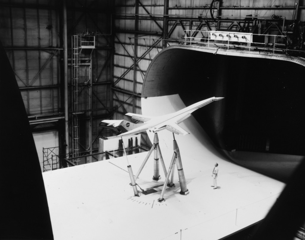
As rocket research gained importance in the 1940’s the capabilities were extended from subsonic to supersonic and even hypersonic research. Even today the importance of aerodynamics research is obvious as one drives past the 14×22 foot subsonic wind tunnel on the way to the main gate.The 1930s in the USA were a golden age for aeronautics. Before World War I, the US government and military did not place high priority on aeronautics research. In fact the total research spending between 1908 and 1913 totalled a measly $435,000 compared to a whopping $28 million spent by Germany. Thus put the US behind countries like Brazil, Chile, Bulgaria, Spain and Greece [4].
All of this changed when aeronautical research started to kick-off at NACA, specifically at Langley Research Center. In the 1930’s aerodynamicist Eastman Jacobs developed a systematic way of designing airfoil shapes, and to this day standard wing shapes are designated with a NACA identification number.During the 1930s various airshows and flying competitions in Europe sparked competition to design the fastest aircraft. For example, the Schneider Trophy was an annual competition for seaplanes and was won on three occasions by Supermarine aircraft designed by Reginald J. Mitchell, who later used the insights gained from these competitions to design the iconic WWII fighter Supermarine Spitfire. However, at some point the speed records hit a wall just shy of the speed of sound and it was unclear if it was possible to break the “Sound Barrier” at all.
Researchers were having a tough time figuring out why drag increased and lift decreased as an aircraft approached the speed of sound. It was not until 1934 that a young Langley researcher John Stack captured the culprit on a photograph of a high-speed wind tunnel test of an airfoil.
As the aircraft airspeed approaches the speed of sound, small pockets of supersonic flow develop on the suction surface of the airfoil as the airflow accelerates over the curved profile. For thermodynamic reasons these pockets of supersonic flow terminate in normal shock waves and the ensuing increase in pressure exacerbates the adverse pressure gradient on the suction surface. Ultimately, this leads to premature boundary layer separation and thereby decreases lift and increases drag (see figure below). John Stack was the first person to capture this phenomenon on film and paved the way for supersonic flight in the years to come.
Other major accomplishments of NASA Langley Research Center include:- The idea of designing specific research aircraft dedicated to supersonic flight, which led to the world’s first transonic wind tunnel
- Simulation and testing of landing in lunar gravity using the Lunar Landing Facility
- The Viking program for Mars exploration
- 5 Collier trophies, the U.S. aviation’s more prestigious award, including the 1946 trophy to Lewis A. Rodert, Lawrence D. Bell and a certain Chuck Yeager for the development of a wing deicing system. Fred Welck won the trophy in 1929 for the NACA cowling, an engine cover for drag reduction and improved engine cooling
- The grooving of aircraft runways to improve the grip of aircraft tires by reducing aquaplaning, now an international standard for all runways around the world.
But as Elon Musk rightly points out, Space X’s exploits would not be possible without NASA’s achievements throughout the last 100 years and its continuing support of the private sector. In fact, NASA made one of it’s first steps into public-private partnerships as early as the 1940’s with the development of the Bell X-1, the first manned aircraft to break the sound barrier.
In that respect join me in congratulating NASA to its centennial and to more exciting aerospace developments for the next 100 years!
References
[1] “Nasa langley test gantry” by Unknown – NASA. Licensed under Public Domain via Wikimedia Commons – https://commons.wikimedia.org/wiki/File:Nasa_langley_test_gantry.jpg#/media/File:Nasa_langley_test_gantry.jpg
[2] “Shooting for a better understanding of aircraft targets, ALDF hit its target” by Sam MacDonald (2015). http://www.nasa.gov/langley/shooting-for-a-better-understanding-of-aircraft-landings-aldf-hit-its-target . Published 8 May 2015. Accessed 22 May 2015.
[3] “Full Scale Wind Tunnel (NASA Langley)” by Photocopy of photograph (original in the Langley Research Center Archives, Hampton, VA [LaRC]) (L73-5028). Licensed under Public Domain via Wikimedia Commons – https://commons.wikimedia.org/wiki/File:Full_Scale_Wind_Tunnel_(NASA_Langley).jpg#/media/File:Full_Scale_Wind_Tunnel_(NASA_Langley).jpg
[4] “Nine notable facts about NACA” by Joe Atkinson (2015) http://www.nasa.gov/larc/nine-notable-facts-about-the-naca. Published 30 March 2015. Accessed 22 May 2015.
[5] “14×22 Subsonic Tunnel NASA Langley” by Erik Axdahl Axda0002. Licensed under CC BY-SA 2.5 via Wikimedia Commons – https://commons.wikimedia.org/wiki/File:14x22_Subsonic_Tunnel_NASA_Langley.jpg#/media/File:14x22_Subsonic_Tunnel_NASA_Langley.jpg
[6] “Transonic flow patterns” by U.S. Federal Aviation Administration – Airplane Flying Handbook. U.S. Government Printing Office, Washington D.C.: U.S. Federal Aviation Administration, p. 15-7. FAA-8083-3A.. Licensed under Public Domain via Wikimedia Commons – https://commons.wikimedia.org/wiki/File:Transonic_flow_patterns.svg#/media/File:Transonic_flow_patterns.svg
[7] “Pista Congonhas03” by Valter Campanato/ABr – Agência Brasil. Licensed under CC BY 3.0 br via Wikimedia Commons – https://commons.wikimedia.org/wiki/File:Pista_Congonhas03.jpg#/media/File:Pista_Congonhas03.jpg
“Big data” is all abuzz in the media these days. As more and more people are connected to the internet and sensors become ubiquitous parts of daily hardware an unprecedented amount of information is being produced. Some analysts project 40% growth in data over the next decade, which means that in a decade 30 times the amount of data will be produced than today. Given this this trend, what are the implications for the aerospace industry?
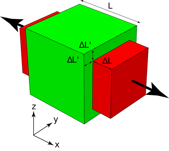
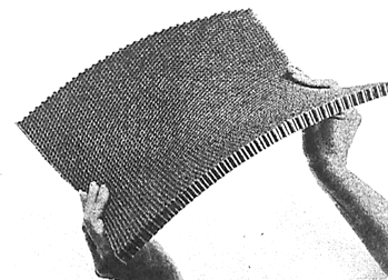
In bending, a similar phenomenon occurs known as anti-clastic curvature. If you have ever tried bending a thin, beam-like structure made out of a soft material e.g. a rubber eraser, you might have noticed that the beam wants to develop opposite curvature in the transverse direction to the main bending axis. The structure morphs into some form of saddle shape as shown in the figure. The phenomenon occurs because the bending moment applied by the person in the picture causes tension in the top surface and compression in the bottom surface in the direction of applied bending. From the Poisson’s effect we know that this induces compression in the top surface and tension in the bottom surface in the transverse direction. By analogy, this is exactly the reverse of the bending moment applied by the hands and so the panel bends in the opposite sense in the transverse direction.
References
(1) http://www.astm.org/HTTP/IMAGES/70104.gif
(2) http://csmres.co.uk/cs.public.upd/article-images/Premium-nordenham.jpg
(3) Kim et al. (2012). “Continuous Tow Shearing for Manufacturing Variable Angle Tow Composites”. Composites: Part A, 43, pp. 1347-1356
When I was travelling in Chile a short while ago I took a flight from the capital Santiago de Chile to the city of Calama in the Atacama dessert. What was interesting about this flight, was that on its way to Calama the airplane landed for a short stop in Copiapó. Immediately after leaving the runway the doors opened, a couple of people got off and were immediately replaced by others already waiting on the tarmac. I had never seen this metro-style system of operating an airline before and was surprised how efficient this system was being implemented. I was also struck by the albeit ludicrous idea of operating an air-bus (no pun intended) style fixed travel route between major European cities, say London-Paris-Madrid-Rome-Vienna-Berlin-London, with people hopping on and off at their pleasure. How cool would that be?
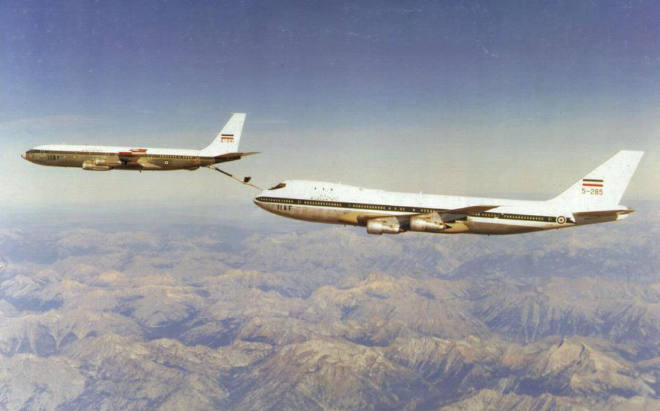
I understand that the fixed costs of this system would be relatively high, and making any money on the tight margins that airliners are operating on would be incredibly tough. However, research is currently ongoing to realise a similar system for long distance travel. One possibility is exploiting the concept of air-to-air refuelling that has been used by the military and the Air Force One for many years. A collaborative European study Research on a Cruiser-Enabled Air Transport Environment (Recreate) has been running simulations at the National Aerospace Laboratory (NLR) in Amsterdam since 2011. The aim of these simulations is to investigate the technical challenges and potential savings of refuelling airliners in midair.
This may sound like a fanciful notion but given that airlines have to cut the 2005 carbon emissions in half by 2050 it well worth looking into these radical ideas. In fact, preliminary results of the study show that fuel burn could be reduced by 11% to 23% if airliners could be refuelled by tanker planes. Passenger safety being paramount in civil aircraft the military concepts currently in use will have to be adapted to meet the required reliability standards. In military environments the tanker flies ahead of the aircraft and supplies fuel through a boom from above. To reduce the likelihood of collisions a forward extending boom refuelling from the bottom is the solution preferred by the researchers. In this manner the civil aircraft does not fly in the wake of the tanker, which could affect turbulence and passenger comfort. Furthermore, the responsibility and training remains with the tanker pilots who have better visibility of the refuelling process when flying from the rear.
The researchers also intend to take the concept one step further by exchanging cargo and passengers in midair, thus getting closer to the idea of an airline metro system. This research envisions a new type of large cruising airliner that is fed by much smaller feeder planes. In this scenario, the larger cruisers fly fixed routes over large distances, while the smaller feeders exchange passengers, crew and cargo with the cruiser in midair. One major challenge with the scheme is that the cruiser aircraft will require an incredible durable engine with low fuel consumption. Such a system does not seem to be economically feasible using current chemically fuelled jet engines. The greater amounts of fuel to be stored has to be offset by a larger engine and airframe, which naturally increases the loads on components in turn requiring thicker sections and structures. Thus, with current gas-fuelled engines you are very much caught in the downward payload spiral that is so frustrating in rocketry.
But what if the cruisers are propelled by nuclear engines? Well the efficiency of the system improves significantly. In fact the efficiency gains are so great that a large cruiser could fly continuously for a whole year just on a few litres of gasoline. Powered by nuclear fusion a cruiser could stay airborne for months, and passengers could hop on and off a continuously airborne global fleet of international airlines.
And it turns out that in October 2014 Lockheed Martin’s Skunk Works announced that they could have a prototype fusion reactor ready within five years and a working production engine within ten. The obvious “buts” are that that a fusion process requires temperatures in the millions of degrees in order to separate ions from electrons which creates hot plasma in the process. In fusion the danger is not a nuclear fallout as is the case in fission. The problem with fission engines is that they require shielding to protect passengers and also carry the dangers of spreading radioactive material in the event of a crash. In a fusion engine the difficulty is in stabilising the plasma and safely containing it in the reactor to guarantee the fusion of ions. The Skunk Works are currently working on an eloctro-magnetic suspender system to guarantee a stable reaction. Furthermore, neutrons that are emitted in the fusion process can damage the materials in the containing structure and turn them radioactive. Thus materials that minimise this radioactivity are needed. Finally, the fusion reactors need to be miniaturised from the scale of family houses to something more akin of an SUV. In that event fusion reactors will also become an interesting propulsion method for spaceships and other spacecraft that have limited space for power generation.
While this is all science fiction for now it presents an interesting option for facilitating a global metro-style airline system. And how cool would that be?
Adrian Bejan is a Professor of Mechanical Engineering and Materials Science at Duke University and as an offshoot from his thermodynamics research he has pondered the question why evolution exists in natural i.e. biological and geophysical, and man-made i.e. technological realms. To account for the progress of design in evolution Prof. Bejan conceived the constructal law, which states that
For a finite-size flow system to persist in time (to live), its configuration must evolve (freely) in such a way that it provides easier access to the currents that flow through it.
In essence a new technology, design or species emerges so that it offers greater access to the resources that flow i.e. greater access to space and time. The unifying driver behind the law is that all systems that output useful work have a tendency to produce and use power in the most efficient manner.

The Lena Delta. Photo Credit Wikipedia [1]
A difficulty in studying natural evolution is that it occurs on a time-scale much greater than our lifetime. However, in a recent study published in the Journal of Applied Physics Prof. Bejan and co-workers show that the shorter technological evolution of airplanes allows us to witness the phenomenon from a bird’s-eye view. Interestingly, as a “flying machine species” the evolution of airplanes follows the same physical principles of evolution that are observed in birds and that can be captured elegantly using the constructal law. For example, the researchers found that
- Larger airplanes travel faster. In particular the flight velocity of aircraft is proportional to its mass raised to the power 1/6 i.e.
- The engine mass is proportional to body mass, much in the same way that muscle mass and body mass are related in animals
- The range of an aircraft is proportional to its body mass, just as larger rivers and atmospheric currents carry mass further, and bigger animals travel farther and live longer.
- Wing-span is proportional to fuselage length (body length), and both wing and fuselage profiles fit in slender rectangles of aspect ratio 10:1
- Fuel load is proportional to body mass and engine mass, and these scale in the same way as food intake and body mass in animals.
This overall trend is depicted nicely in Figure 1 which shows the size of new airplane models against the year they were put into service. It is evident that the biggest planes of one generation are surpassed by even bigger planes in the next. Based on economical arguments it can be assumed that each model introduced was in some way more efficient in terms of passenger capacity, speed, range, i.e. cost-effectiveness than the previous generation of the same size. Thus, in terms of the constructal law the spreading of flow is optimised and this appears to be closely matched with the airplane size and mass. Similarly, Figure 2 shows that both birds and aircraft evolve in the same way in that the bigger fly faster. Thus, the evolution of natural and technological designs seems to have converged on the same scaling rules. This convergent design is also evident in the number of new designs that appear over time. At the start of flight the skies were dominated by swarms of insects of very different design. These were followed by a smaller number of more specialised bird species and today by even fewer “aircraft species”. Combining these two ideas of size and number, it seems that the new are few and large, whereas the old are many and small.
The key question is why engines, fuel consumption or wing sizes should have a characteristic size?
Any vehicle that moves and consumes fuel to propel it depends on the function of specific organs, say the engines or fuel ducts, that interact with the the fuel. Because there is a finite size constraint for all these organs the vehicle performance is naturally constrained in two ways:
- Resistance i.e. friction and increasing entropy within the organs. This penalty reduces for larger organs as larger diameter fuel ducts have less flow resistance and larger engines encounter less local flow problems. Thus, larger is generally better
- On the flip side the larger the organ the more fuel is required to move the whole vehicle. But the more fuel is added the more the overall mass is increased and the more fuel you need, and so on. This suggests that smaller is better.
From this simple conflict we can see that a size compromise needs to be reached, not too small and not too large, but just right for the particular vehicle. In essence what this boils down to is that larger organs are required on proportionally large vehicles and small organs on small vehicles. Thus, as more and more people intend to travel and move mass across the planet the old design based on small organs becomes imperfect and a more efficient, larger design for the new circumstances is required.
Overall, the researchers conclude that the physical principles of evolution define the viable shape of an aircraft. Thus, the fuselage and the wing must be slender, the fuselage cross-section needs to be round and the wing span must be proportional to the fuselage length. A famous outlier that broke with these evolutionary trends of previous successful airplanes was the Concorde with its long fuselage, massive engines and short wingspan. Rather than attempting to achieve an overall superior solution the designers attempted to maximise speed, and thereby compromised passenger capacity and fuel efficiency. Only 20 units were ever produced and due to lack of demand and safety concerns the Concorde was retired in 2003. Current aircraft evolution manifested in the Boeing 787 Dreamliner, 777X and Airbus A350 XWB are rather based on combining successful architectures of the past and with new concepts, that allow the overall design to remain within the optimal evolutionary constraints. Thus, it is no surprise that in an attempt to make aircraft larger and at the same time more efficient, the current shift from metal to carbon fibre construction is what is needed to elevate designs to a higher level.
References
[1] http://en.wikipedia.org/wiki/Lena_Delta_Wildlife_Reserve#mediaviewer/File:Lena_River_Delta_-_Landsat_2000.jpg
[2] Bejan, A., Charles, J.D., Lorente, S. The evolution of airplanes. Journal of Applied Physics, 116. 2014.
Vanity Fair recently featured an excellent article on Air France Flight 447 that crashed into the Atlantic in 2009. It is a long read, but if you have 30 min to spare it will be a great educational investment.
The author, William Langewiesche, does a good job at weaving multiple aspects of aeronautics, such as cockpit design, ergonomics, the physics of flight and pilot training, into a story that is ultimately about the role of human fallibility in a system that is governed by automation. This is a topic that I find highly fascinating and will only become more pertinent in the future as computers take over increasing number of tasks in the cockpit. In fact, the psychological impact on the pilots and the effect of automation on the piloting profession on a whole remain uncertain.
The article features extensive coverage of the pilots’ conversation and provides a riveting account of what transpired in the cockpit prior to the crash. In this way the article brings to light some of the human misjudgements that ultimately led to the catastrophe. On some occasions I found myself cringing at the incredulity of the events that transpired, futilely hoping that the pilots would turn the situation around and save the 228 passengers onboard, while fully aware that hindsight makes all mistakes appear tauntingly clear.
The reason for the plane crash was a classic case of aerodynamic stall brought on by the pilot climbing too quickly and exceeding the critical angle of attack, depending on the operating conditions in the range of 13-16°. Even when the angle of attack was at an incredible 41°, the aircraft was rolling from side to side, the alarm system was screaming “STALL”, the cockpit was shaking violently due to the turbulent flow separation over the wings and the aircraft was losing altitude at a rate of 4,000 feet per minute, each one a tale-tell signs of aerodynamic stall, the pilots did not know what was happening with the airplane!
What brought the aircraft into this situation in the first place? The pitot static tube used as sensors for the flight speed had been clogged by a hail storm, which automatically took the fly-by-wire system out of the auto-pilot, disabled the automatic stall recovery system and returned the controls back to the pilots. At this point had the pilots continued the modus operandi of keeping the aircraft at the same altitude with the engines at constant thrust, nothing would have happened. It is ironic, that the only thing the pilots needed to do to keep the plane safely in the air was nothing. It is unclear why one of the pilots decided to climb to a higher altitude and especially why this was done so rapidly, but this ultimately triggered the aerodynamic stall of the wings.
William Langewiesche argues that increasing automation “de-skills” pilots, essentially rendering them incapable of flying an aircraft without support systems. I find the following section especially interesting:
“For commercial-jet designers, there are some immutable facts of life. It is crucial that your airplanes be flown safely and as cheaply as possible within the constraints of wind and weather. Once the questions of aircraft performance and reliability have been resolved, you are left to face the most difficult thing, which is the actions of pilots. There are more than 300,000 commercial-airline pilots in the world, of every culture. They work for hundreds of airlines in the privacy of cockpits, where their behavior is difficult to monitor. Some of the pilots are superb, but most are average, and a few are simply bad. To make matters worse, with the exception of the best, all of them think they are better than they are. Airbus has made extensive studies that show this to be true.”
So how has this been dealt with in the past?
“First, you put the Clipper Skipper [daring WW II fighter pilots] out to pasture, because he has the unilateral power to screw things up. You replace him with a teamwork concept—call it Crew Resource Management—that encourages checks and balances and requires pilots to take turns at flying. Now it takes two to screw things up. Next you automate the component systems so they require minimal human intervention, and you integrate them into a self-monitoring robotic whole. You throw in buckets of redundancy. You add flight management computers into which flight paths can be programmed on the ground, and you link them to autopilots capable of handling the airplane from the takeoff through the rollout after landing. You design deeply considered minimalistic cockpits that encourage teamwork by their very nature, offer excellent ergonomics, and are built around displays that avoid showing extraneous information but provide alerts and status reports when the systems sense they are necessary. Finally, you add fly-by-wire control. At that point, after years of work and billions of dollars in development costs, you have arrived in the present time. As intended, the autonomy of pilots has been severely restricted, but the new airplanes deliver smoother, more accurate, and more efficient rides—and safer ones too.”
This essentially causes a shift in the piloting profession…
“In the privacy of the cockpit and beyond public view, pilots have been relegated to mundane roles as system managers, expected to monitor the computers and sometimes to enter data via keyboards, but to keep their hands off the controls, and to intervene only in the rare event of a failure. As a result, the routine performance of inadequate pilots has been elevated to that of average pilots, and average pilots don’t count for much[…]Once you put pilots on automation, their manual abilities degrade and their flight-path awareness is dulled: flying becomes a monitoring task, an abstraction on a screen, a mind-numbing wait for the next hotel.[…] For all three [pilots on Air France Flight 447], most of their experience had consisted of sitting in a cockpit seat and watching the machine work.”
We all know that automation is indispensable going forward. It is too valuable a system and has made aviation the safe mode of transport it is today. However, the issues raised above will need to be addressed within the near future. Possible solutions may be requiring pilots to turn off auto-pilot for a certain number of flights, while another approach may be to improve the machine-human interaction in the cockpit. In either case, I think it is important to point out that catastrophes such as Air France Flight 447 are outliers, black swans, six-sigma events that are not likely to repeat again in the same detail. In fact, the roots of the next catastrophe may lie somewhere completely different and thus are impossible to predict.
References
[1] William Langewiesche, “The Human Factor”, Vanity Fair, October 2014. http://www.vanityfair.com/business/2014/10/air-france-flight-447-crash
This blog has focused much on the technical side of aviation. One of the biggest drivers in civil aviation is passenger safety and the last 40 years have brought tremendous advances on this front, with aviation now being the safest mode of transport. A lot of this has to do with the deep understanding engineers have about the strength of materials (static failure, fatigue and stability), the complexities of airflow (eg. stall), aeroelastic interaction (eg. flutter and divergence) and the control of aircraft. Furthermore, appropriate systems have been put in place do deal with uncertainty and monitoring the structural health of aircraft.
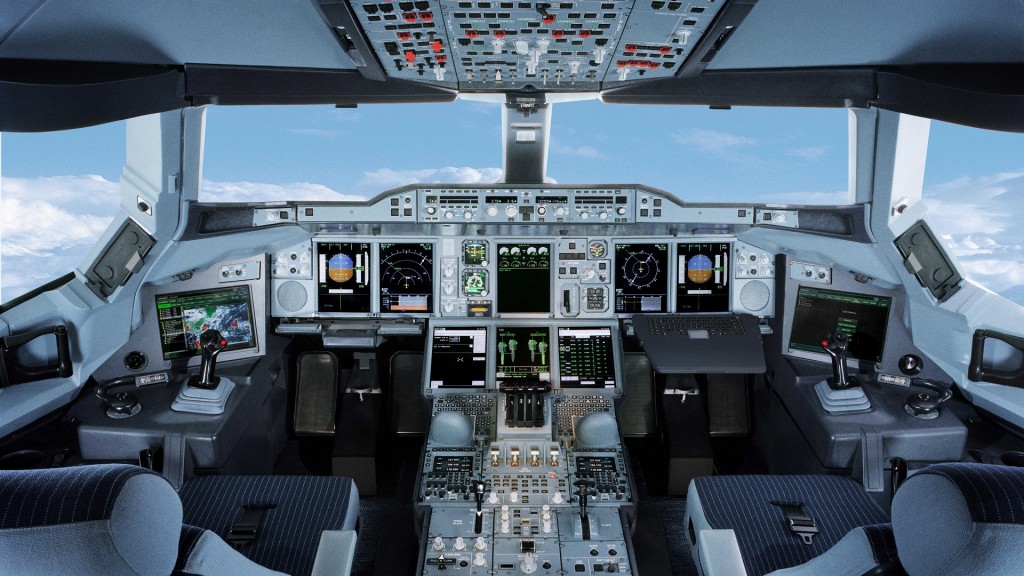
Anyone who has been inside a commercial aircraft cockpit can appreciate the technology that goes into controlling a jumbo jet. The amount of switches, levers and lights is mind-boggling. A big part of the high-tech that goes into commercial aircraft are automated control systems that keep the aircraft up in the air and automate parts of flight that require little input from pilots (eg. cruising at altitude). One could argue that human beings are fallible systems and therefore we should relinquish as much control as possible to automated computer systems. Get the computer to do everything it can and only allow humans to intervene in situations that require human judgement. In short if it’s technically possible, let’s automate.
The problem with this argument is that automating a process does not completely remove humans from the picture. If any form of human interaction is required at some point, the pilot still needs to be vigilant at all times in order to be ready to act swiftly when needed. Only focusing on automation and forgetting about the human-system interaction is bound to get us into trouble. This is a great risk of modern day specialisation. Focusing solely on your niche of the problem and forgetting factors from other scientific disciplines – “For a man with a hammer, everything looks like a nail”.
So, we require more than a hammer in our toolbox. Until we have automated the whole flight envelope to statistical perfection we need to be thinking about the way that systems and humans interact in the cockpit. Guaranteeing infallibility of the technical side is not enough. In fact, the aerospace industry was one of the first to introduce checklists into cockpits that are used to guide the pilots through specific manoeuvres and prevent avoidable mistakes and procedures that are easily overlooked or forgotten under pressure. It is incredible how successful you can be by continuously trying not to be stupid. The checklist system has worked so well that it is now being used in hospitals with amazing results. In the same manner the interaction between machine and humans has a lot to do with human psychology. As engineers we are generally aware of ergonomic design in order to create functional and user-friendly products. I have yet to see a university course that teaches the psychology of automation or human misjudgement in general to engineering students.
However, it is not hard to imagine what automation can do to our brains. For anybody that uses cruise control in their cars, are you more or less likely to remain vigilant once the cruise control is set and you’ve taken the foot off the accelerator? I think it’s fair to say that most people will lose focus on what’s happening on the road once they are less engaged. In this way the risk in automation is that it can lead to boredom and loss of attention to detail. This is especially dangerous if we have been lulled into a sense of false comfort and start relinquishing all control in the belief that the system will take care of everything.
Now why am I bringing this up? Because for exactly these reasons Flight 3407 lost control (aerodynamic stall) and crashed in 2009, killing everyone on board. According to the National Transportation Safety Board the likely cause of the accident were, “(1) the flight crew’s failure to monitor airspeed in relation to the rising position of the low-speed cue, (2) the flight crew’s failure to adhere to sterile cockpit procedures, (3) the captain’s failure to effectively manage the flight, and (4) Colgan Air’s inadequate procedures for airspeed selection and management during approaches in icing conditions. [1]” Apart from the fourth reason everything suggests a simple failure to pay attention. The pilot had not noticed that the airplane lost air speed during automated decent. Upon being alerted by the stick shaker, an anti-stall system, he inadvertently pulled the shaker in the wrong direction thereby further reducing airspeed and stalling the plane from it could not recover. In fact, a 1994 National Transportation Safety Board review of thirty-seven accidents involving airline crews found that in 84% of the cases inadequate monitoring of controls was a contributing factor.
There is a lot to learn from these failures and given the excellent track record of the aviation industry these findings will undoubtedly lead to better procedures. However, apart from better procedures we also need to holistically educate the engineers of tomorrow to look past purely technical design and incorporate research from psychology. Research into how this is best achieved is currently ongoing but for now there is something we can all take away from this: don’t simply automate something because we can, but because we should.
References
[1] http://www.ntsb.gov/doclib/reports/2010/aar1001.pdf
Nassim Nicholas Taleb coined the term “Antifragility” in his book of the same name. Antifragility describes objects that gain from random perturbations, i.e. disorder. Taleb writes,
Some things benefit from shocks; they thrive and grow when exposed to volatility, randomness, disorder, and stressors and love adventure , risk, and uncertainty. Yet, in spite of the ubiquity of the phenomenon, there is no word for the exact opposite of fragile. Let us call it antifragile. Antifragility is beyond resilience or robustness. The resilient resists shocks and stays the same; the antifragile gets better. This property is behind everything that has changed with time: evolution, culture, ideas, revolutions, political systems, technological innovation, cultural and economic success, corporate survival, good recipes (say, chicken soup or steak tartare with a drop of cognac), the rise of cities, cultures, legal systems, equatorial forests, bacterial resistance … even our own existence as a species on this planet. And antifragility determines the boundary between what is living and organic (or complex), say, the human body, and what is inert, say, a physical object like the stapler on your desk.
In greek mythology the sword of Damocles is an example of a fragile object as a single large blow will break it, a phoenix can resurrect and is therefore robust, while the Hydra is an antifragile serpent because for every head that is chopped off, two will grow back in its place. Antifragile systems are extremely important in complex environments where black swan events can wreak havoc. Black swans are rare but highly consequential events; the “fat tails” located far away from the mean in a probability distribution.
Often black swan events happen due to non-linear behaviour or a confluence of multiple drivers. Non-linearity is inherently difficult for our brains to comprehend which makes black swan events basically impossible to predict beforehand. In structural mechanics for example, it took researchers years to realise that the buckling behaviour of cylindrical shells, such as fuselage sections, is an inherently non-linear structural phenomenon, and that linear eigenvalue solutions could result in drastic over-predictions of the load carrying capacity. Theodore von Kármán managed to explain the physics of the problem through a series of papers in the first half of the 20th century, by first qualitatively investigating the phenomenon using simple experiments and then formalising the theory in what are now the non-linear von Kármán equations.
But what does this have to do with the engineering design process?
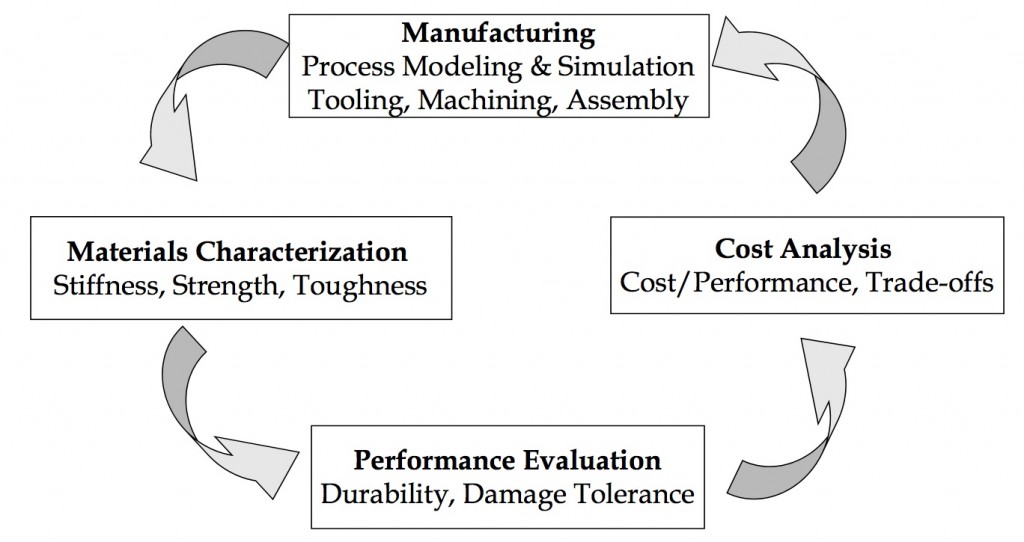
Well, by nature the design process is iterative. Ideally we strive towards creating a system of concurrent engineering. Tasks performed by the design, structural and manufacturing engineers are parallelised and integrated to reduce the development time to market, and reach the best compromise between different technical and financial requirements. Despite this parallelisation, the design process within each of these departments is still highly iterative as engineers across different functional fields interact and refine the design. Most importantly, throughout the whole aircraft design process individual components and sub-assemblies are experimentally tested to verify the design under critical load conditions. Examples of these are cabin section pressurisation fatigue tests and catastrophic tests of whole wing sub-assemblies. The information of these stress tests is fed back into the design system to close the loop and inform the next stage in the design.

Design Cycle (Courtesy of Wikipedia)
Taleb calls this form innovative work “stochastic tinkering”. It is a means of experimenting and adjusting a system, aiming to discover fact “A” but in the process also learning about “B”. Stochastic tinkering is by nature antifragile as good aspects of a design are retained while failures are quickly removed; very much an analog of the evolutionary process in nature.
Of course there is a good deal of deterministic analysis involved in engineering design. However, preliminary design calculations are often based on “back-of-the-envelope” methods. The aim of these preliminary calculations is to constrain the design space to a smaller feasible region. The design is then refined further in the detail design stage using more advanced techniques such as Finite Element Analysis or Computational Fluid Mechanics. Crucially, no matter how beautiful the design works on paper if it doesn’t perform in the validation tests it has failed.
Finally, the notion of designing for black swan events is inherently incorporated in the design process. In structural analysis of aircraft hundreds of different load cases are tested individually and in confluence to make sure the structure can withstand the worst imaginable/historic loading scenario multiplied by a factor of safety. Furthermore, the “safe-life”, “fail-safe” and “damage tolerant” design frameworks create a checklist for components which:
- are absolutely not allowed to fail during service (e.g. landing gear and wing root)
- are allowed to fail, as structural redundancies are in place to re-direct load paths (e.g. wing stringers and engines)
- and components that are assumed to contain a finite initial defect size before entering service that may grow due to fatigue loading in-service. In this manner the aircraft structure is designed to sustain structural damage without compromising safety up to a critical damage size that can be easily detected by visual inspection between flights.
This approach is limited to known load cases. Therefore, the reserve factors of 1.2 for limit load and 1.5 for ultimate load exist to provide a margin of safety against uncertainty, i.e. things we can not quantify, the “known unknowns” and “unknown unknowns”.
Historically, catastrophic in-service failures have been and continue to be used as invaluable learning experiences. Thus, “fat tail” catastrophic events are continually being used to eradicate weaknesses and improve the design. This, in essence, is the definition of antifragility. As terrible as the loss of life in the DeHavilland Comet and other crashes have been, without them, airplane travel would not be as safe as it is today.
The flight envelope of an aeroplane can be divided into two regimes. The first is rectilinear flight in a straight line, i.e. the aircraft does not accelerate normal to the direction of flight. The second is curvilinear flight, which, as the name suggests, involves flight in a curved path with acceleration normal to tangential flight path. Curvilinear flight is often known as manoeuvring and is of greater importance for structural design since the aerodynamic and inertial loads are much higher than in rectilinear flight.
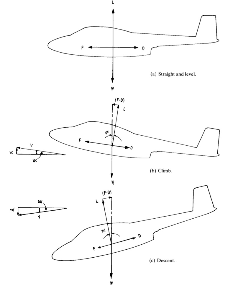
As the aircraft moves relative to the surrounding fluid a pressure field is set up over the entire aircraft, and not only over the wings, that acts to keep the aircraft afloat. This aerodynamic pressure always acts normal to the outer contour of the skin but the resultant force can be resolved into two forces acting tangential and normal to the direction of flight. The sum of the forces normal to the direction of flight give rise to the lift force L, which offsets the weight of the aircraft i.e. offsets the weight of the aircraft W. The tangential components give the resultant drag force D, which in powered flight must be overcome by the propulsive force F. The resultant force F includes the thrust generated by the engines, the induced drag of the propulsive system and the inclination of the line of thrust to the direction of flight. In basic mechanics the aircraft is simplified into a point coincident with the centre of gravity (CG) of the aircraft with all forces assumed to act through the centre of gravity. If the net resultant of a force is offset from the CG then a resultant moment will also act on the aircraft. For example, the lift generated by the wings is generally offset from the centre of gravity of the aircraft and may thus produce a net pitching moment that has to be offset by the control surfaces. Figure 1 below shows as a simplified free body diagram of an aircraft in level flight, climb and descent.
Note that the lift is only equal and opposite to the weight in steady and level flight, thus:
and
In steady descent and steady climb the lift component is less than the weight, since only a component of the weight acts normal to the direction of flight and because by definition lift is always normal to both drag and thrust. Also in climbing the thrust must be greater than the drag to overcome the component of weight acting against the direction of flight and vice versa in descent. Thus in a climb:
and
and in descent
,
This situation is schematically represented in Figure 1 by the relative sizes of the different arrows. In general we can imagine the weight being balanced by the lift force L and the difference between the thrust F and the drag D. A bit of manipulation of the two equations for climb or descent above gives the same expression,
such that,
The latter expression is clearly obtained if Pythagoras’ rule is applied to the vector triangles that include (F-D) and L in Figure 1.
Figure 1 also shows velocity diagrams depicting the relationship between true air speed V, tangential to the direction of flight, and the rates of climb and descent and
respectively. We can combine these velocity triangles with the forces triangles to obtain simple equations for the rates of climb and descent,
and
such that or
.
This expression can also be used to gain some insight into the driving factors behind gliding flight. In this case the net propulsive force F is zero such that the expression becomes,
which may be approximated to
since the angle of descent in gliding is typically very shallow. Therefore the gliding efficiency of a sailplane depends on maximising the lift to drag ratio L/D. If the ascending thermals are equal to or greater than this rate of descent than the glider can continuously maintain or even gain in altitude.
An aircraft may of course increase its speed along the direction of rectilinear flight in which case the thrust force F must be greater than the vector sum of the drag and the component of the weight. A more interesting scenario are accelerated flight where the acceleration occurs as a result in change in direction rather than a change in speed. By definition, in vector mechanics a change in direction is a change in velocity and therefore defined as acceleration, even if the magnitude of the speed does not change. A change in the flight path is achieved by changing the magnitude of the overall lift component or by differences in lift between the two wings, away from the equilibrium condition depicted in Figure 1. This change can either be obtained by a change in true airspeed or by changing the angle of attack of the wings relative to the airflow. Consider the simple banked turn in Figure 2 below.
As the aircraft banks the lift force normal to the wings is turned through an angle from the vertical weight vector. Since the centripetal acceleration acts horizontally and the weight acts vertically we can use simple trigonometric relations to find the radius of turn:
such that
. It is also obvious that the more steeply banked the turn the more lift will be required from the wings since,
such that increase in engine power is needed to maintain constant speed under this flight condition. This is one of the reasons why fighter jets that require manoeuvres with very tight radii have such short and stubby wings. Small radii if turn R and thus high banking angles require increases in lift and therefore increase the bending moments acting on the wings.
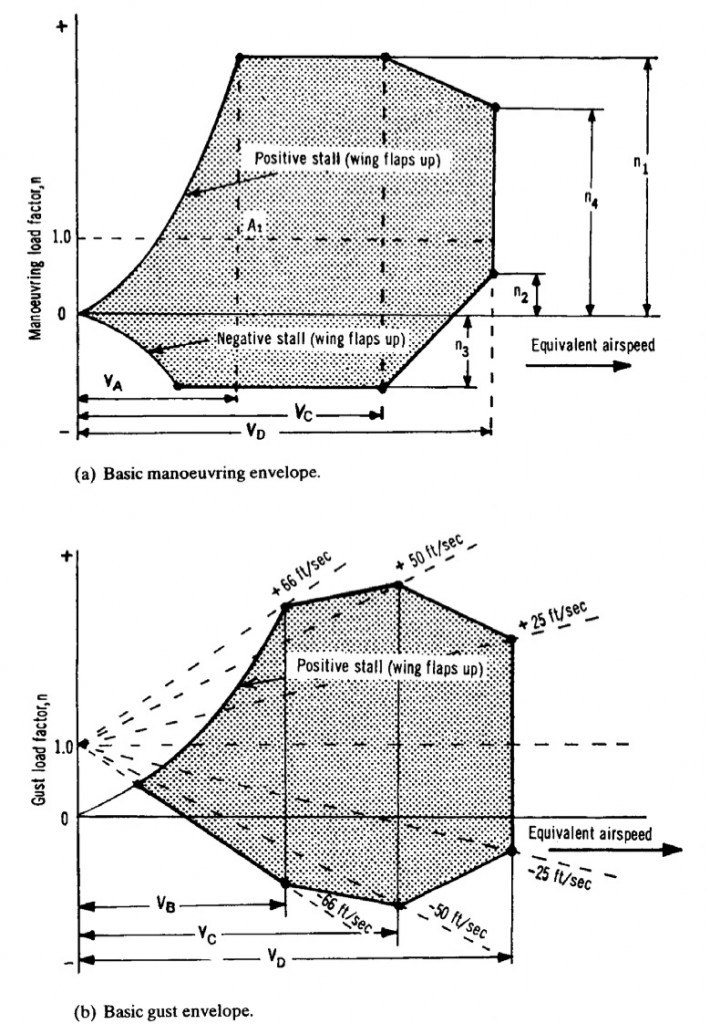
In reality the airplane is subjected to a large variety of different combinations of accelerations (rolls, pull-ups, push-overs, spinning, stalling , gusts etc.) at different velocities and altitudes. In classical mechanics free fall is expressed as having an acceleration 0f -1g and level flight is denoted as 0g. The aeronautical engineer differs from this convention in order to make the comparison between lift and weight simpler. This means that free fall is denoted by 0g and level flight by 1g. The ratio between lift and aircraft weight is called the load factor n, where , i.e. n = 0 for free fall, n = 1 for level flight, n > 1 to pull out of a dive and n < 1 to pull out of a climb. The overall load spectrum of an aircraft is captured graphically by so called velocity – load factor (V-n) curves. The outline of these diagrams are given by the possible combinations of load factor and velocity than an aircraft will be expected to cope with. For example Figure 3a shows the basic V-n diagram for symmetric flight (asymmetric envelopes exist for rolls etc. but are not covered here).
The envelope is constructed from the positive and negative stall lines which indicate, respectively, the maximum and minimum load that can be achieved because of the inability of the aircraft to produce any more lift. Thus,
where is the density of the surrounding air and
is the wing surface area. The limiting factor
also known as the maximum expected service load is defined by
or 2.5, whichever is greater, with W the max take-off weight.
,
and
are defined as the maximum manoeuvre speed ( the speed above which it is unwise to make full application of any single flight control), the design cruise speed and the maximum dive speed, respectively. The intersection between the horizontal line
and the left curve of the envelope is also of special significance since it represents the stall speed at level flight. In general the limit load factor must be tolerable without detrimental permanent deformation. The aircraft must also support an ultimate load (=limit load x safety factor) for at least 3 seconds. The safety factor is generally taken to be 1.5.
Finally, Figure 3b shows a typical gust envelope. A gust alters the angle of attack of the lifting surfaces by an amount equal to where w is the vertical gust velocity. Since the lift scales with the angle of attack up to the point of aerodynamic stall, the inertia forces applied to structure are altered by the gust winds. The gust envelope is constructed with the same stall lines as the basic manoeuvre envelope and different gust lines are drawn radiating from n = 1 at V = 0. Note that the design gust intensities reduce as the velocity increases, with the intention that the aircraft is flown accordingly. In the gust envelope
is replaced with
, representing the design speed at maximum gust intensity.
References
(1) Stinton, D. The Anatomy of the Airplane. 2nd Edition. Blackwell Science Ltd. (1998).
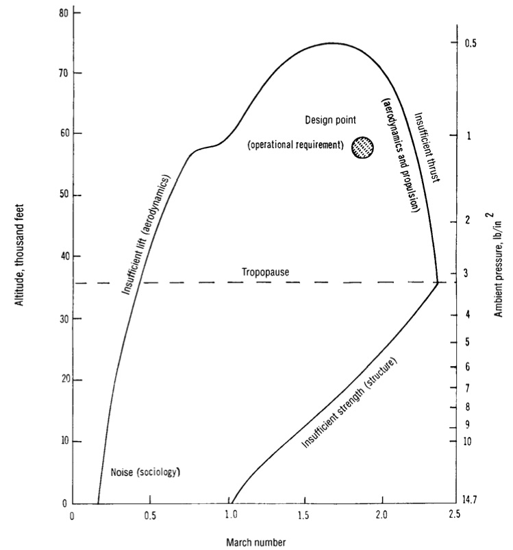
Every aircraft has a certain operational environment, including aspects of flight and ground operations, that it is designed to serve in throughout its lifetime. For example the operational requirements of a fighter jet are much more strenuous than those of a commercial airliner. The flight regime is broadly defined by the range of different flight speeds and altitudes called the flight envelope. Within this range lies the so-called design point, which is the operational environment in which the aircraft is expected to spend most of its time in. An example plot of a typical flight envelope is shown in Figure 1. The outline of the envelope defines the limit of performance for a specific aircraft configuration. The left edge defines the minimum speed required to keep the aircraft flying at a certain altitude. The small dip in the curve at around Mach 1.0 denotes the increase in drag caused by small supersonic pockets close to the leading edge of the airfoil. Supersonic flow is inherently terminated by a shock wave that causes an increase in fluid pressure. At speeds around Mach 1.0 these shockwaves are still located on the airfoil surface and therefore exacerbate the adverse pressure gradient across the suction surface, leading to premature boundary layer separation and higher pressure drag. The top of the curve marks the region where the minimum level speed is equal to the maximum speed that can be sustained by the aircraft’s engine and structural capability. The declining curve on the right indicates the envelope where speed is limited first by the power of the engines and then by the weight of the aircraft i.e. as the aircraft speed increases so do the loads on the airframe and therefore the material required (mass) to sustain these loads. The flight envelope in Figure 1 can be drawn for any aircraft and will be different depending on the unique role e.g. commercial transport, freight, fighter, bomber etc. Today the different roles of aircraft are no longer as clear-cut since aircraft are expected to fulfil multiple roles (e.g. freight and commercial transport) for economic reasons.
The operating environment influences the overall shape of the aircraft which can broadly be broken down into three design segments: aerodynamic shape of wings, fuselage and controlling surfaces; the choice of propulsion; and the structural layout. Naturally, for a given design point and payload there will be conflicting requirements and optimal solutions for each area individually. However, an important point to realise is that an aircraft design will only be successful if these three design factors are dealt with concurrently i.e. the optimal compromise must be found.
The commutative property is valid for the above equation i.e. the shape of the aircraft is defined by the operational requirements, similarly the shape given to an aircraft restricts the functions that the aeroplane is capable of. This means that in the early parts of the design process the engineers need to be aware what variables can be fixed and where flexibility can be maintained to limit limitations if the design environment changes.
This picture is often complicated by a additional demands that have nothing to do with the flight envelope. Thus under the given flight envelope the engineers deal with added issues of economic requirements, manufacturability, passenger ergonomics and safety, airfield requirements, environmental and noise regulation. For example, an airline operator wishes to maximise profit on each flight and therefore a major incentive for commercial aircraft manufacturers’ is to cater to this need and not the goal of engineering state-of-the-art technology. Freight and travel airlines are in the business of making money from the payload they transport from A to B. The higher the profit per kg of payload carrier the better for the airline. In this respect the dry mass of the aircraft is of critical importance for profitability. The lower the dry mass of the airline the more payload can be carried over a certain distance for a given amount of fuel. Thus not only is the fuel efficiency improved (lower costs) but the revenue is also increased by carrying more goods. This is one of the reasons why lightweight composite materials are such a big driver for future aircraft design.
References
(1) Stinton, D. The Anatomy of the Airplane. 2nd Edition. Blackwell Science Ltd. (1998).
Sign-up to the monthly Aerospaced newsletter
Recent Posts
- Podcast Ep. #49 – 9T Labs is Producing High-Performance Composite Materials Through 3D Printing
- Podcast Ep. #48 – Engineering Complex Systems for Harsh Environments with First Mode
- Podcast Ep. #47 – Möbius Aero and MμZ Motion: a Winning Team for Electric Air Racing
- Podcast Ep. #46 – Tow-Steered Composite Materials with iCOMAT
- Podcast Ep. #45 – Industrialising Rocket Science with Rocket Factory Augsburg
Topics
- 3D Printing (4)
- Aerodynamics (29)
- Aerospace Engineering (11)
- Air-to-Air Refuelling (1)
- Aircraft (16)
- Autonomy (2)
- Bio-mimicry (9)
- Case Studies (15)
- Composite Materials (25)
- Composites (7)
- Computational Fluid Dynamics (2)
- Contra-Rotation (1)
- Design (2)
- Digitisation (2)
- Drones (1)
- Education (1)
- Electric Aviation (11)
- Engineering (23)
- General Aerospace (28)
- Gliders (1)
- Helicopters (3)
- History (26)
- Jet Engines (4)
- Machine Learning (4)
- Manufacturing (12)
- Military (2)
- Modelling (2)
- Nanomaterials (2)
- NASA (2)
- New Space (11)
- News (3)
- Nonlinear Structures (1)
- Novel Materials/Tailored Structures (14)
- Personal Aviation (5)
- Podcast (45)
- Propulsion (9)
- Renewable Energy (2)
- Renewables (1)
- Rocket Science (17)
- Satellites (8)
- Shape Adaptation (1)
- Smart Materials (1)
- Space (12)
- Space Junk (1)
- Sport Airplanes (2)
- Startup (19)
- STOL (1)
- Structural Efficiency (5)
- Structural Mechanics (1)
- Superalloys (1)
- Supersonic Flight (2)
- Technology (18)
- UAVs (2)
- Virtual Reality (2)
- VTOL (3)
- Privacy & Cookies: This site uses cookies. By continuing to use this website, you agree to their use.
To find out more, including how to control cookies, see here: Cookie Policy

![NASA Langley subsonic wind tunnel [2]](https://aerospaceengineeringblog.com/wp-content/uploads/2015/05/14x22_Subsonic_Tunnel_NASA_Langley-1024x322.jpg)
![Transonic shock wave [4]](https://aerospaceengineeringblog.com/wp-content/uploads/2015/05/Transonic_flow_patterns.svg_.png)
![Grooved airport runway [3]](https://aerospaceengineeringblog.com/wp-content/uploads/2015/05/Pista_Congonhas03-1024x697.jpg)

