The treatment of defects in aircraft structural design has been an important aspect in aircraft structural design during the last 50 years. Various different catastrophic events have led to key insights that now shape the design philosophy for primary aircraft structures. One of these is the distinction between Safe-Life and Fail-Safe structures. Safe-Life components are designed to go through their service life without cracks and defects playing a major role in the stress state of the component. Thus, the required fatigue life to initiate a crack is kept below the anticipated service life. This design approach is mainly used for components for which there are no back-ups in place and where failure would lead to the loss of the aircraft. A typical example of a Safe-Life component is the landing gear and this remains one of the reasons why landing gears are made from high-strength steel for which engineers have a long history of structural data. The second “Fail-Safe” design philosophy assumes that any real manufacturing process will induce defects within the part that, even if microscopic, may vary between different batches and may grow during the service life. Thus the Fail-Safe components are structurally designed to withstand all imposed loads up to a certain certain level of defect, known as the “critical size”, which can usually be detected by eye and act as stress concentrators. In this manner critical components are continuously monitored at specific service intervals to make sure that no crack exceeds the critical defect size, and is subsequently replaced if this happens. Furthermore, crack propagation analyses are employed in order to ascertain how many flights/load cycles it will take to grow a crack to the critical size. Most of these insights stem from the experience engineers have gained during the last 50 years with metal aircraft and in fact there was quite a steep learning curve during the transition years from wood to metal aircraft.
Today we are facing a similar transition from metal to mostly fibre reinforced plastics and other advanced materials whose failure mechanisms are often much more complex than that of metals. First, in metallic structures a crack typically initiates at an imperfection or stress concentration and then propagates under fatigue loading until final failure. The damage morphology in composites however is completely different: a large number of microscopic defects, such as micro-cracks that occur during post-cure shrinkage of the resin are present over a large volume of the material and these may develop into different failure mechanism over time. Second, most metals have a ductile failure mechanism such that overloading can visually be detected by the onset of plastic deformation. Therefore there is often a warning period between a structure being overloaded and failing catastrophically. Fibre reinforced plastics, especially carbon fibre composites on the hand fail by more brittle and therefore sudden mechanisms. Third, while a major driver of component design for metal structures is crack growth, which can be predicted quite accurately today using analytical methods or Finite Element codes, fibre reinforced plastics have a plethora of other failure mechanisms and manufacturing defects that are equally important. Some examples are fibre breakage, matrix cracks, matrix-fibre debonding, delaminations, voidage, misplacement of plies, lack of impregnation and fibre waviness. Interlaminar failures such as delaminations are especially important since they can occur very quickly when a laminate is loaded through the thickness, for example at stringer run-outs, in corner-radii of C-spars or simple impact events such as tool drop in the factory. Since there are typically no reinforcing fibres in the perpendicular direction the structural integrity is only guaranteed by the weak matrix. Due to this inherent weakness different plies may literally be pulled apart at their lamination interfaces. Techniques such as through thickness reinforced such as 3D braiding, Z-Pinning or nano-fibre reinforcement are currently being researched. Under compressive forces these delaminations may form blisters, so called delimitation buckling, which can easily propagate along the lamination interface leading to disintegration of the part.

Fig. 1 Delamination Buckling in Composite Laminate
Finally, different failure mechanisms actually interact making accurate predictions of the failure load including a defect extremely difficult. Furthermore, even experimental data for laboratory sized specimens cannot readily be used for real-sized components since the scaling up of structures has been found to greatly alter the dominant failure mechanism. Finally, failure sites in fibre reinforced plastics are often internal meaning that an engineer will not be able to detect them by simple visual investigation during service intervals. As a result, the increasing use of fibre reinforced plastic construction during the recent years and near future means more sophisticated evaluation techniques are required for guaranteeing safe design and operation of aircraft. Another key question is how these new types of defects can be taken into account reliably in structural design?
Compared to metallic materials composites have a very unique characteristic in that the material and structure/part are created simultaneously. This means that the amount of imperfections in the part is greatly dependent on the manufacturing process. In composite materials the fail-safe design philosophy of degrading the material properties to that including a “critical defect size” is not only important to reduce the probability of failure as in metallic structures but also because a manufacturing process free from imperfections would be financially prohibitive. Thus, the degree of process and quality control depends greatly on the safety requirements of the industry. For example, the high-volume and competitive automobile sector needs to guarantee passenger safety while keeping manufacturing costs at a minimum. In the aerospace industry however the mass of components is absolutely critical and takes precedence over the manufacturing costs. As a result the automobile industry relies more on out-of-autoclave infusion processes that allow high production volumes such as Resin Transfer Moulding, while the aerospace industry currently relies on the high-temperature, high-pressure curing environments of the autoclave that allow the manufacture of high performance parts with low, controlled level of imperfections.
Non-destructive testing (NDT) methods are often employed to detect defects inside or on the surface of a material. In general they are broken down into surface methods, bulk volume methods and global methods. These methods are typically used at the end of the manufacturing process as a quality control measure or during the life of the part to monitor and assess its fitness for continuing use. Surface methods include visual inspection techniques such as scanning the surface for obvious cracks, porosities, resin rich/starved regions or surface waviness. This is often coupled with endoscopes to examine remote or difficult to access locations. Furthermore a common technique is dye penetrant inspection where a dye is applied to external surfaces and illuminated with an ultraviolet light in order to highlight cracks on the surface that the dye has crept into. This technique was quite popular for aero engine components but is inherently quite time and labour intensive.
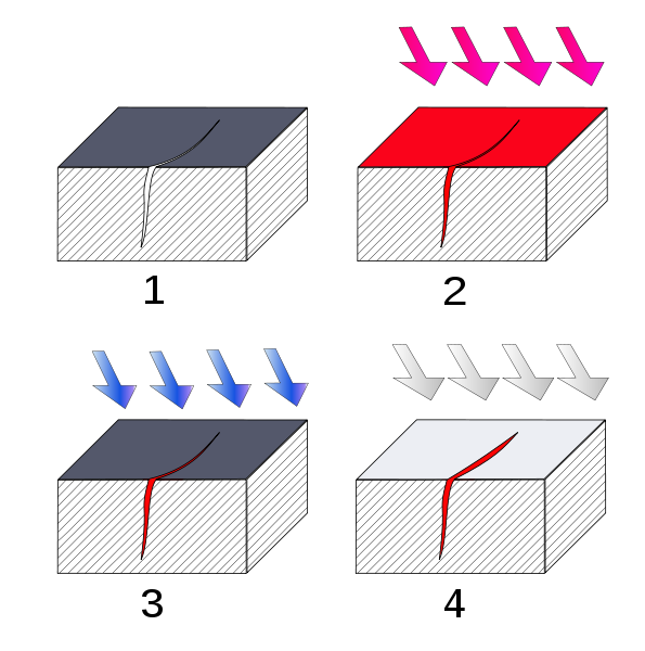
1. Section of material with a surface-breaking crack that is not visible to the naked eye.
2. Penetrant is applied to the surface.
3. Excess penetrant is removed.
4. Developer is applied, rendering the crack visible. (1)
Bulk volume methods range from the simple tap test to ultrasonic screening to the most sophisticated X-ray and computer tomography techniques. The choice of the method depends greatly on the type of defect that is to be detected and criticality of cycle time and production costs. Simple surface defects, core crush in sandwich structures may easily be detected using visual techniques, while tap tests can be used very effectively to determine delaminations or large internal voids. In a tap test the component is tapped lightly with a hard object such as a coin or ring which emits a very dull sound if a delimitation lies beneath the testing point. On the other hand the exact location and size of a delimitation, possible contaminations, voids or micro-porosities can only be detected with ultra-sonic or C.T. techniques. In this respect ultra-sonic scanning has developed to be the most widely-used NDT technique in the aerospace industry due to its high detection fidelity, compactness and relative low-cost compared to C.T. techniques. In ultra-sonic scanning ultrasound is projected into a component and by measuring the strength and time delay of the echo it is possible to detect inclusions (air, solid objects etc.) that differ from the host composite material.

Fig. 3. Principle of ultrasonic testing. LEFT: A probe sends a sound wave into a test material. There are two indications, one from the initial pulse of the probe, and the second due to the back wall echo. RIGHT: A defect creates a third indication and simultaneously reduces the amplitude of the back wall indication. (2)
One of the drawbacks of ultrasonic scanning is that some sort of coupling agent (typically water or a gel) is required between the probe and surface of the part to guarantee a high-quality reading. Furthermore, the scanning of large areas can be very time intensive even with the use of multi-probe ultrasonic arrays that can be rolled across a surface or controlled by a robotic arm, such that this technique is typically restricted to critical or highly-stressed components. Finally, CT techniques are currently only widely used in academia where they can give very useful insight into the exact 3D morphology of a cured part and show how and where cracks are initiated and when they propagate. Some pieces of equipment like Synchrotron radiation computed tomography at the University of Southampton can produce extremely detailed 3D plots and videos of parts under load that are very useful to help researchers understand what drives failure in composite materials.
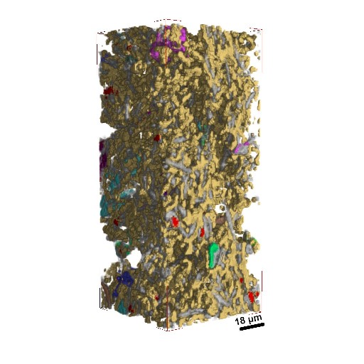
Fig. 4. 3D Synchrotron Image (3)
Finally, in recent years global methods such as structural health monitoring have been a hot research topic. In structural health monitoring sensors such as strain gauges or fibre-bragg grating systems are embedded within the structure and provide real time data on the stress state. In this manner the health of the structure can be monitored in real time and service intervals and replacement parts be installed at the required times. However, these systems can probably not be embedded throughout an entire aircraft and require an incredible amount of storage to cope with the continual data stream.
Understanding the detrimental effects of imperfections and the damage mechanisms is essential in order to take full advantage of the benefits that high performance composites have to offer. In this respect non-destructive testing is a very valuable tool for investigating and mapping the internal condition of a component. One of the challenges facing the aerospace and automobile industries in the future is deciding what detail of non-destructive testing is required to guarantee the structural integrity of the products to a high degree of probability during the entirety of its service life and balancing this against the cost that the specific techniques incur.
Image Credit and Sources
(1) Wikipedia, http://en.wikipedia.org/wiki/File:Ressuage_principe_2.svg
(2) Wikipedia, http://en.wikipedia.org/wiki/File:UT_principe.svg
(3) Institute of Materials Science and Technology – Vienna University of Technology, http://mmc-assess.tuwien.ac.at/mmc/?mid_detail=99
