“You could say: What could we possibly do next? You look back at history and say: All the shelves must be full now! We must have the capabilities to do everything we need. And yet, we still go on…It’s your generation that is going to Mars. So please, can you get on with it and do it, because I want to enjoy it from the augmented reality that other engineers are going to produce.” — Ian Lane
![]() This episode features Ian Lane, Senior Expert in Composite Analysis for Airbus UK. Ian has more than 40 years of experience in the aerospace industry and his career has taken him from British Hovercraft to British Aerospace, Westland Helicopters and finally to his current role at Airbus. On top of this broad aerospace background, Ian’s specialty are modern composite airframes and he was the lead stress engineer on the Airbus A400M and Airbus A350. Ian is also a Visiting Professor in Aerospace Engineering at the University of Bristol, and a great example of an industry leader who knows how to inspire the next generation of young engineers. Indeed, Ian is actively involved with the Airbus Fly Your Ideas campaign, and a regular attendee at many international research conferences.
This episode features Ian Lane, Senior Expert in Composite Analysis for Airbus UK. Ian has more than 40 years of experience in the aerospace industry and his career has taken him from British Hovercraft to British Aerospace, Westland Helicopters and finally to his current role at Airbus. On top of this broad aerospace background, Ian’s specialty are modern composite airframes and he was the lead stress engineer on the Airbus A400M and Airbus A350. Ian is also a Visiting Professor in Aerospace Engineering at the University of Bristol, and a great example of an industry leader who knows how to inspire the next generation of young engineers. Indeed, Ian is actively involved with the Airbus Fly Your Ideas campaign, and a regular attendee at many international research conferences.
In this episode Ian and I discuss:
- his career progression from apprentice to Senior Expert at Airbus
- the incredible safety record of the aerospace industry
- why the demise of Concorde wasn’t a step backwards
- how Airbus fosters innovation and out-of-the-box thinking
- why inclusion and diversity in engineering are so important
- and much, much more
I hope that you enjoy this conversation as much as I did. If you enjoy the Aerospace Engineering Podcast you can support it by leaving a review on iTunes or by becoming a patron.
What have you learned from this episode? Let me know on Twitter by clicking here.
This episode of the Aerospace Engineering Podcast is sponsored by SAMPE North America. SAMPE is a global professional society that has been providing educational opportunities on advanced materials for more than 70 years. SAMPE’s network of engineers is a key facilitator for the advancement of aerospace engineering by enabling information exchange and synergies between aerospace companies. To find out how SAMPE can help you learn more about advanced materials and processes, consider attending the SAMPE 2018 Technical Conference and Expo in Long Beach, California.
Podcast: Play in new window | Download | Embed
Subscribe: Apple Podcasts | TuneIn | RSS
Selected Links from the Episode
- Airbus in Bristol & Filton, UK
- British Hovercraft Company
- Westland Helicopters (for a time known as AugustaWestland and now Leonardo Helicopters)
- Sikorsky Crisis, also known as the Westland Affair
- British Aerospace (now known as BAE Systems)
- The EU TANGO project (overview slides)
- A400M and A350 airframes, and contrasts between the two
- Evolution of composite application at Airbus
- Airbus Helicopters NH90 and Tiger
- Bend-twist coupling in aircraft wings
- Clean Sky initiative
- New aerospace metallic alloys
- Additive manufacturing and bionic 3D printing at Airbus
- Aerospace testing pyramid and virtual testing
- Burt Rutan and Scaled Composites
- A picture history of aviation safety and the “anti-fragile” nature of aircraft design
- Concorde demise and the Concorde Museum
- Airbus Fly Your Ideas
- Diversity at Airbus, Diversity & Inclusion in Engineering
- Women of NASA Lego
- Evolution of flying machines
“There’s been a lot of good press from the science community on self-assembly of atoms. Well, I guess what I’m looking for is self-assembly and disassembly of large-scale structures…There is all sorts of exciting things we can do when [engineering] structures re-configure themselves.” — Prof. Paul Weaver
 This episode features Prof. Paul Weaver, who holds a Bernal Chair in Composite Structures at the University of Limerick in Ireland, and is the Professor in Lightweight Structures at the University of Bristol in the United Kingdom. Lightweight design plays a crucial role in the aerospace industry, and Paul has worked on some fascinating concepts for more efficient aircraft structures. Paul’s research has influenced analysis procedures and product design at NASA, Airbus, GKN Aerospace, Augusta Westland Helicopters, Vestas (and many more), and in this episode we cover some of his past accomplishments and his vision for the future.
Central to this vision is artificial metamorphosis, which is a term that Paul coined to describe structures that re-configure by dis-assembly and re-assembly to adapt and optimise on the fly. Although Paul thinks that this vision of engineering structures is still 50 years into the future, he is well known for his work on a related technology: topological shape-morphing. The simplest example of a morphing structure is a leading edge slat, which is used on all commercial aircraft today to prevent stall at take off and landing. Paul, on the other hand, envisions morphing structures that are more integral, that is without joints and which do not rely on heavy actuators to function. Apart from artificial metamorphosis, Paul and I discuss
- his teenage dreams of becoming a material scientist
- his work with Mike Ashby at Cambridge University on material and shape factors
- interesting coupling effects in composite materials that can be used for elastic tailoring
- his work with Augusta Westland helicopters on novel rotor blades
- why NASA contacted him about his research on buckling of rocket shells
- and much, much more
I hope that you get a feel for Paul’s enthusiasm for aerospace engineering. If you enjoy the Aerospace Engineering Podcast you can support it by leaving a review on iTunes or by becoming a patron.
Please enjoy this wide ranging conversation with Prof. Paul Weaver!
What have you learned from this episode? Let me know on Twitter by clicking here.
Podcast: Play in new window | Download | Embed
Subscribe: Apple Podcasts | TuneIn | RSS
Selected Links from the Episode
- Bernal Institute, University of Limerick
- Paul’s research group at the University of Limerick and the University of Bristol
- Structures: Or Why Things Don’t Fall Down
and The New Science of Strong Materials: Or Why You Don’t Fall Through the Floor
by Prof. J E Gordon
- Prof. Mike Ashby, materials selection using Ashby plots and its geometrical counterpart: shape factors, CES Materials Selector
- Second moment of area
- AugustaWestland AW101 Merlin helicopter that uses bend-twist coupling in the rotor blades to decouple vibration modes
- Bend-twist coupling of a wing-box explained on the Grumman X-29
- Geometrically swept wind-turbine blades for improved performance
- Imperfection sensitivity of cylinders (the introduction of this paper conveys the message)
- Video of collapsing soda can and “scientific” crush test
- Morphing:
- NASA morphing aircraft
- FlexSys wing without flaps
- A project by NASA and MIT on flexible morphing structures
- NASA shape-shifting wings
- A morphing air inlet
- A video featuring Paul talking about his research and vision for artificial metamorphosis
- Some topics related to metamorphosis are:
- The deHavilland Mosquito, the importance of phenolic resins in constructing the Mosquito, and Norman de Bruyne
“If you’re trying to put these structures into orbit, every gram counts. Not just every pound but every gram…So you are making structures that are operating at their margins.” — Dr Chauncey Wu, NASA Langley Research Center
 Today’s conversation features Dr Chauncey Wu, who is a research engineer at NASA Langley Research Center in Hampton, Virginia. Chauncey has worked at NASA for more than 30 years, predominantly in the field of structural mechanics, and has been responsible for designing and testing a number of space structures that have been launched into space. Some examples of his work include structural analyses on the LITE telescope that was launched into space in 1994, as well as the optimisation of rocket propellant tank structures, and conceptual design studies of lunar lander vehicles and habitat structures for the colonisation of the Moon. In this wide-ranging conversation, we discuss:
- Chauncey’s path to NASA as an undergraduate student
- The history of NASA and the cultural shift compared to its predecessor, the NACA
- The reason why rocket science is so hard
- Chauncey’s recent research on a new type of lightweight composite material: tow-steered composites, which could be a game-changer for rocket booster designs
- And much, much more
Please enjoy this wide ranging conversation with Dr Chauncey Wu! If you enjoy the Aerospace Engineering Podcast you can support it by leaving a review on iTunes or by becoming a patron.
What have you learned from this episode? Let me know on Twitter by clicking here.
Podcast: Play in new window | Download | Embed
Subscribe: Apple Podcasts | TuneIn | RSS
Selected Links from the Episode
- NASA Langley Research Center
- NASA Glenn, NASA Goddard, NASA Ames and NASA Marshall
- NASA co-op program
- The NACA (predecessor to NASA)
- Bob Gilruth, Chris Kraft
- Collier Trophy
- Low-Drag Cowling and Fred Weick
- John Stack, Larry Bell, Chuck Yaeger and the X-1
- Slotted-wall wind tunnel
- Richard Whitcomb, the Area Rule and the Supercritical Airfoil
- Science Office for Mission Assessments
- The safety factor
- The history of rocketry and a primer on rocket science and lightweight design
- Tow-steered composites (some further NASA research here and here)
- ISAAC
- Imperfection sensitivity of cylinders (the introduction of this paper conveys the message)
- Video of collapsing soda can and “scientific” crush test
- NASA Shell Buckling Knockdown Factor (video)
I am happy and excited to announce a new project on the Aerospace Engineering Blog. To go along with the usual blog posts, I will now be releasing regular podcast episodes that feature conversations with engineers and researchers in industry and academia to reveal their fascinating real-world stories of innovation, and provide a glimpse into the future of the industry by discussing cutting-edge research and promising new technologies. This episode is just a quick primer of what I have in mind, and the first “real” episode will be released in a couple of days.
If you have comments about the episodes or want to provide general feedback on the podcast, then please let me know on Facebook. If you find yourself enjoying the conversations, then I would appreciate a quick review on iTunes or Stitcher. This helps others find the podcast online. I will of course be publishing all episodes through this homepage as well, and you will receive notifications when I publish new episodes through the newsletter.
You will be able to find archives of all published episodes here, and each episode post will contain show notes with links to further material of the topics discussed.
If you enjoy the Aerospace Engineering Podcast you can support it by leaving a review on iTunes or by becoming a patron.
Podcast: Play in new window | Download | Embed
Subscribe: Apple Podcasts | TuneIn | RSS
This is the second post of a three-part series (see first part) on great engineers, inventors, pioneers, aviators and pilots that have shaped the history of aviation. Each profile provides a little nugget of information about their key achievements and invites you to learn more about these pioneering men and women by clicking on the embedded links. While this is not a comprehensive list, I have tried to include a broad spectrum of names, including the classics we have all heard of, as well as some of the less well known, and in my opinion, underrated pioneering aviators. Enjoy!

Amelia Mary Earhart
Role: Pioneering US Pilot
Born: July 24, 1897 Disappeared: July 2, 1937 Declared Dead: January 5, 1939
Best known for: Early aviation records, first woman to fly solo across the Atlantic Ocean
Alma Mater: Columbia University
In 1918, Amelia Earhart and a friend visited an air show associated with the Canadian National Exhibition in Toronto. The flying exhibition was led by a WWI flying ace, who pulled off a stunt by diving at Earhart and her friend, who were watching from an isolated clearing, seemingly trying to scare them and cause them to run. Earhart did not budge, and as the red airplane swooshed overhead, it seemingly whispered something to Earhart, as she would later recall. Two years later, the air racer Frank Hawks gave Earhart a ride in an airplane that would change her life for good—she now knew she had to fly. By working a variety of odd jobs, Earhart earned enough money to afford flying lessons (1921) with Neta Snook in a Curtiss JN-4. In 1922, Earhart purchased a secondhand Kinner Airster biplane, which she flew to 14,000 feet, setting a new world record for female pilots (not yet having received her license). After a series of medical problems throughout the mid-1920s, Earhart returned to flying in 1928, in an attempt to fly across the Atlantic Ocean. Charles Lindbergh had just completed this feat in 1927, and the book publisher George P. Putnam, who published Lindbergh’s biography “WE”, was keen to sponsor Earhart’s flight. Earhart accompanied pilot Wilmer Stultz on a flight from Newfoundland to South Wales in a Fokker F.VIIb, strictly speaking as a passenger, but with the additional duty of keeping flight logs. After this flight, members of the press started to refer to Earhart as “Lady Lindy”, and she embarked on a lecture tour throughout 1928/1929, published a book alongside Putnam, and began appearing publicly in brand endorsements. Nevertheless, Earhart was committed to breaking records on her own. In 1928, she became the first woman to fly solo across the USA and back. In 1931, she set a world altitude record at 18,415 feet in a Pitcairn PCA-2. Finally, in 1932, Earhart set off from Newfoundland to fly solo across the Atlantic Ocean in a Lockheed Vega 5B, landing in Northern Ireland just shy of 15 hours later, thereby repeating Lindbergh’s feat of 1927. Upon this success, Earhart received many accolades such as the Distinguished Flying Cross and Gold Medal of the National Geographic Society. With her increased fame, she developed many high profile friendships, such as with First Lady Eleanor Roosevelt, who shared Earhart’s advocacy for women’s causes in society. Even though these record flights seem like stunts today, the media coverage they gained were crucial in convincing the public that flying was for them too, and not just for daredevils. Indeed, Earhart invested time and money in realising the Ludington Airline, which flew the first air service between New York and Washington, DC. In 1936, Earhart starting planning a round-the-world flight, choosing a longer equatorial route of 29,000 miles, than had previously been flown by a team of US Army aviators in 1924 over 175 days. A Lockheed Electra 10A was built to her specifications with a larger fuel tank. In 1937, a first attempt failed after the first leg, when Earhart ground-looped (rapid yawing and rolling) during take-off, severely damaging her Lockheed Electra. The same year, Earhart started her second attempt, departing eastward from Miami, successfully stopping in South America, Africa, India, South East Asia and New Guinea. After completing 22,000 miles of her journey, only 7,000 miles remained. On July 2, Earhart and her navigator Fred Noonan intended to fly from New Guinea to Howland Island, but through a series of poor planning, technical faults, human errors and communication misunderstandings, the approach to Howland, via radio navigation with a US plane stationed on the island, was not successful. The fate of Earhart and Noonan remains unclear but current research and speculation suggests that the Electra either ran out of fuel and crashed into the Pacific, or that Earhart managed to land on one of the neighbouring island. The mystery of Earhart’s crash maintains a world-wide interest in her story and fuels treasure hunts to this day.

Kraftt Arnold Ehricke
Role: Pioneering Space Scientist
Born: March 24, 1917 Died: December 11, 1984
Best known for: D-1 Centaur, NEXUS rocket, space station design
Alma Mater: Technical University of Berlin
Kraft Ehricke was a German rocket engineer and one of the very early advocates for space colonisation. Inspired by Fritz Lang’s movie “Woman in the Moon”, he formed his own rocket society at the young age of 12. He obtained a degree in Aeronautical Engineering from the Technical University of Berlin, studying celestial mechanics and nuclear physics from scientific greats such as Hans Geiger and Werner Heisenberg. During WWII, he worked at Nazi Germany’s infamous Peenemünde rocket research centre, and then emigrated to the USA under Operation Paperclip in 1947. Initially, Ehricke continued to develop the V-2 rocket for the US Air Force alongside Wernher von Braun in Huntsville, Alabama, and the two engineers wrote a book about how humans would travel to Mars using a spaceship ferry system. In 1952, Ehricke transitioned from government service to the private sector, working for Bell Aircraft and Convair. At Convair he designed the first upper-stage-booster using liquid hydrogen and oxygen, the D-1 Centaur. Realising the terrible cost structures of disposable rockets, Ehricke led the design of the NEXUS reusable concept rocket at General Dynamics, and also participated on Project Orion, which attempted to design a nuclear propulsion rocket. Ehricke was a true “big thinker” and visionary, conducting a long, multi-year study of the Moon, and drawing up plans to colonise the Moon as the seventh continent using nuclear-powered freight transporters and envisioning fusion-energy-powered cities. Quite fittingly, Ehricke was buried in space, when a small rocket placed part of his cremate remains in orbit.

Jacob Christian Hansen Ellehammer
Role: Engineer, Inventor and Aviation Pioneer
Born: June 14, 1871 Died: May 20, 1946
Best known for: Ellehammer semi-biplane
Jacob Ellehammer had a rather unusual path to aviation. Initially trained as a watchmaker in Copenhagen, Denmark he began working as an electronic mechanic and incorporated his own company in 1898, producing cigarette and beverage dispensers. However, Ellehammer’s mind was too curious to be constrained to a single discipline and so he began tinkering with mechanical devices, producing his first motorcycle in 1904. Using the skills and knowledge gained from building a motorcycle, he then devised the world’s first air-cooled radial engine—a three-cylinder design which was later upgraded to a five-cylinder design in 1907. In 1905, he built a monoplane with a large, triangular wing fitted with one of his engine designs. In 1906, Ellehammer evolved this design into a “semi-biplane” with a single unbroken triangular main wing, with another triangular wing mounted above it that connected to the main wing at the three corners. The pilot was suspended beneath this contraption like a pendulum, such that the aircraft could be controlled by shifting the pilot’s weight from side to side. Unaware of the achievements of the Wright brothers, Ellehammer managed a short, tethered, hopping flight of 42 m at the relatively low altitude of 0.5 m. A year later, Ellehammer invented a triplane version (three triangular wings), which was capable of untethered flight (record 300 m), and in 1912 he built a helicopter, which had the capabilities of hovering in mid-air, although it is unclear if the machine was capable of moving horizontally.

Anton Herman Gerard “Anthony” Fokker
Role: Dutch Aircraft Designer
Born: April 6, 1890 Died: December 23, 1939
Best known for: Eindecker monoplane, Dr.1 triplane, D.VII biplane
Anthony Fokker was born on the island of Blitar, at the time part of the Dutch East Indies, now Indonesia. But as a young boy his family returned to the Netherlands. Lacking formal technical education, Fokker’s achievements can largely be attributed to his autodidact nature (he did not complete high school but preferred tinkering with mechanical devices), native inventiveness and a spark of genius. One apocryphal (not factual) story suggests that he developed the machine gun synchroniser (to prevent bullets from hitting propeller blades) just 48 hrs after receiving the assignment. Balancing his lack of technical training was his philosophy of rapid trial and error. Fokker was a skilled pilot himself, and so by flying his own designs he was able to quickly iterate, and also actively incorporate the opinions and advice of fighter pilots and other engineers. Fokker’s interest in flying stemmed from a Wilbur Wright exhibition flight that Fokker, age 18, saw in Paris. At age 20, Fokker enrolled in the automotive polytechnic school in Mainz, Germany where he built a series of three “Spider” aircraft, which he used to obtain his flying certificate and then brought him notoriety in his home town of Haarlem, by flying the Spider around the church tower. In 1912, Fokker founded his first company in Berlin but later relocated to Schwerin, renaming the company Fokker Werke GmbH. At the outbreak of WWI, the German authorities seized his factory but Fokker remained as the director and chief designer. During WWI, Fokker’s company produced about 700 military planes, and all of Germany’s flying aces—Voss, Immelmann, Bölke, von Richthofen (the Red Baron)—flew Fokker aircraft. To this day, the Eindecker monoplane, the D.VII and the Dr.I triplane (flown by von Richthofen) are considered to be the best airplanes of WWI. Due to the ban on flying machines in Germany after WWI—the Fokker D.VII was the only plane singled out by name in the Treaty of Versailles for its immense destructive power—Fokker emigrated to the US, where he focused on the design and production of commercial transportation aircraft. His most famous aircraft design during this period was the Fokker F.VII trimotor (with one propeller under each wing and one at the front), one of the most successful passenger aircraft of the 1920’s-1930’s. Indeed, many a pioneering flight of that period was flown in one of Fokker’s designs—the first non-stop transcontinental flight across the US (Fokker T-2), the first flight over the North Pole (Fokker F.VIIa/3m), and an endurance flight of 150 hrs that tested aerial refuelling (Fokker Question Mark).

Yuri Alexeyevich Gagarin
Role: Russian Cosmonaut
Born: March 9, 1934 Died: March 27, 1968
Best known for: First human in outer space, first human to orbit Earth
Alma Mater: Saratov Industrial Technical School (1955), Chkalov Air Force Pilot’s School (1957)
Yuri Gagarin was the best advertisement the Soviet Union could ask for at the height of the Cold War. Born into a rural peasant family working on a collective farm, Gagarin became the first human being in space and an international celebrity—epitomising the philosophy of status irrelevance that the Soviet Union stood for. As the pilot of the Vostok 1 capsule, Gagarin’s 108 min orbital flight on April 12, 1961 ultimately proved that humans could endure in new environments—the immense forces acting during take-off and atmosphere re-entry, and the strange condition of weightlessness in orbit. The radio communication between Gagarin and the launch control room,
Korolev: “Preliminary stage….. intermediate….. main….. lift off! We wish you a good flight. Everything is all right.”
Gagarin: “Поехали!” (Poyekhali!—Let’s go!).
became famous in the Eastern Bloc nations, and the phrase “Poyekhali” was thereafter used to denote the beginning of the Space Age. After receiving many accolades, including the Soviet Union’s highest honour (Hero of the Soviet Union), Gagarin was later responsible for training future cosmonauts. He tragically died in 1968 when his MiG-15 training jet crashed.

John Herschel Glenn Jr.
Role: American Astronaut and Fighter Pilot
Born: July 18, 1921 Died: December 8, 2016
Best known for: First American in orbit, distinguished fighter pilot
Alma Mater: Muskingum College (1962), University of Maryland
John Glenn was introduced to the world of aviation at the tender age of eight, when his father took him on an airplane flight. Fascinated by flying, Glenn started to build model airplanes from balsa wood kits and entered Muskingum College in 1939 to study engineering. While at Muskingum, Glenn earned a private flying license, and when the Japanese attacked Pearl Harbour, Glenn quit college to enlist in the Army Air Corps and later transferred to the US Marine Corps. In 1943, Glenn joined the WWII war effort in the Marine Fighting Squadron 155, flying F4F Wildcat fighters and F4U Corsairs on 57 combat missions in the Pacific. Shortly after the war, Glenn served in Northern China in Marine Fighting Squadron 218 before working as a flight instructor in Texas and Virginia. But with the outbreak of the Korean War, he was once again ordered into active service. He flew 63 missions with the Marine Fighter Squadron 311 in an F9F Panther and 27 missions as an exchange pilot to the Air Force in the F-86 Sabre. Glenn was a highly distinguished fighter pilot during the Korean War, shooting down 3 MiG aircraft in the last nine days of the war alone, but was also notorious for his ability to attract enemy fire, twice returning with more than 250 bullet holes in his aircraft, which earned him the nickname “Magnet Ass”. Based on his achievements, Glenn was selected for the Navy’s test pilot school in Patuxent River, Maryland, setting a new transcontinental speed record from Los Alamitos to New York in 3 hrs 23 min, the first transcontinental flight with an average supersonic speed. In 1959, Glenn was chosen as one of the Mercury 7, the first batch of astronauts, and on February 20, 1962 became the first American to orbit the Earth, circling it three times during the Friendship 7 mission. This mission did not go entirely smoothly, as the automatic-control system failed after the first orbit, and a faulty sensor indicated that the Friendship 7’s heat shield had come loose so that the ground controllers decided to leave the solid-fueled retrorocket packet in place to stabilise the heat shield. Glenn continued working for NASA on the early Apollo programme and was especially valuable to the Space Program as a national iconic figure, but he retired from NASA in 1964 to enter politics. He was elected US Senator for Ohio in 1974 and served for 24 years. In 1998, still serving as a senator, Glenn became the oldest person to fly in space as crew on the Discovery space shuttle. Alongside six Distinguished Flying Crosses and 18 Air Medals, he also received the Presidential Medal of Freedom in 2012.

Robert Hutchings Goddard
Role: Inventor and Rocket Pioneer
Born: October 5, 1882 Died: August 10, 1945
Best known for: First liquid-fueled rocket
Alma Mater: Worcester Polytechnic Institute (1908), Clark University (1911)
Historically, the very early developments of airplanes and rockets took very different routes. While the pioneering days of aviation were largely governed by practically minded tinkerers and daredevils that created their own designs, the complexity of rockets and their tendency to blow up, meant that highly trained engineers and scientists made many of the early breakthroughs. Robert Goddard was one such scientist, trained at Worcester Polytechnic and with a PhD in Physics from Clark University, he initially taught Physics at Clark and for a short time at Princeton. Throughout this time he began working through the maths of using rockets for escaping Earth’s gravity, and came to the conclusion that it would be possible with multi-stage rockets fuelled with a solid “explosive material” or with liquid propellants (gasoline and liquid nitrous oxide)—two ideas that he patented in 1914. By 1916 Goddard could no longer afford to foot the cost of his research, so he applied for and eventually received a grant from the Smithsonian Institution to further develop his work on solid-fueled rockets but he also began work on liquid-fueled ones. His grant application, summarising his work up to that point, was later published as his seminal work “A Method of Reaching Extreme Altitudes“. After 15 years of research, he successfully launched the world’s first liquid-fueled rocket on March 16, 1926, to an altitude of 184 feet with a flight time of 2.5 seconds. After another three years of refining his design, he launched another liquid-fueled rocket in 1929, which carried a small camera and a barometer as payload. In the 1930s, he received a Guggenheim Foundation grant, and in 1935 launched a rocket with gyroscopic controls. In total, he and his team launched 34 rockets between 1926 and 1941 reaching impressive heights of 2.6 km and top speeds of 885 km/hr (highest altitude flight in 1937), just missing out on breaking the sound barrier. His ideas on gyroscopic controls, thrust vectoring, liquid fueling and multi-stage rockets anticipated or first developed many of the technologies that made spaceflight possible. Goddard was one of the tragic pioneers that was slightly ahead of his time. While he recognised the full potential of rocketry for atmospheric research, missile technology and space flight, and laid the scientific groundwork to design and construct rockets, he was largely underfunded during his career (probably due to a lack of vision from the government in Washington) and also ridiculed for his ideas by the press. He was posthumously awarded the Daniel Guggenheim Medal in 1964.
Leroy Randle Grumman
Role: Engineer and Industrialist
Born: January 4, 1895 Died: October 4, 1982
Best known for: Grumman Aerospace Co.
Alma Mater: Cornell (1916), MIT
Leroy Grumman studied Mechanical Engineering at Cornell University before enrolling in the Navy and becoming a pilot in 1918. For two years he served as a flight instructor and completed one tour in a bombing squadron, before the Navy sent him to MIT to study the new field of aeronautical engineering. Upon his return, the Navy stationed Grumman at Loening Aeronautical Engineering Corporation in NYC to supervise the construction of 52 Loening M-8 monoplanes, which were being built under contract for the Navy. Grumman quickly rose through the ranks at Loening, becoming a factory manager and then general manager responsible for aircraft design. After Loaning was bought-out by Keystone in 1929, Grumman formed his own company, the Grumman Aeronautical Engineering Corporation, first repairing Loaning amphibian aircraft and then constructing his own designs. The Grumman FF-1 biplane fighter produced for the US Navy introduced the retractable landing gear and enclosed cockpit, and his cooperation with the Naval forces continued for many decades. Some of the pioneering aircraft Grumman produced were Grumman’s first monoplane design, the F4F Wildcat, the first practical folding-wing plane with superior stowage capabilities on aircraft carriers; and the F6F Hellcat fighter which was introduced for WWII in 1942. The folding “Sto-Wing” capability was single-handedly invented by Grumman and showcased his genius as a master engineer. Grumman supposedly worked out a solution to the problem by sticking paper clips into erasers to find the right fulcrum that would make the Sto-Wing possible. Grumman’s company produced more than 30,000 aircraft during WWII. For the Korean War, Grumman produced the Navy’s first jet fighter, the F9F Panther, and the SA-16 Albatross amphibian which was used for search and rescue operations. Grumman’s company is now part of the large Northrop Grumman Corporation.

Sir Geoffrey de Havilland
Role: Aircraft Designer and Industrialist
Born: July 27, 1882 Died: May 21, 1965
Best known for: de Havilland Company
Alma Mater: Crystal Palace School of Engineering (1903)
Continuing from the point made earlier regarding the nature of daredevil aviation pioneers, Geoffrey de Havilland was certainly one of a kind. In 1909, he built his first aircraft, crashed it on its first flight, built a second one and through trial and error, taught himself how to fly. De Havilland eventually sold this second airplane design to the Royal Aircraft Factory, and this airplane then became the F.E.1. In 1914, he became the chief designer at Airco, designing a number of aircraft which all carried his initials: DH. A large number of these aircraft were used by the Allies in WWI. After the automotive business of Airco was bought by BSA Company, de Havilland bought the relevant aerospace assets and formed the de Havilland Aircraft Company. The most significant early designs were the beautiful Moth-series of aircraft, which spawned the beginning of all light sport aircraft. After buying his friend’s (Frank Halford) engine design consultancy, de Havilland began producing its own engines as well, and the first gas turbine jet engine to come out of this new venture (Halford H.1 turbojet, later de Havilland Goblet) powered de Havilland’s first jet, the Vampire, with a unique twin tail-boom construction. The two planes that de Havilland is most famous for are the Mosquito—according to some the most versatile warplane ever built and due to its lightweight plywood construction one of the most unique designs of WWII—and the Comet—the first commercial jet airliner to go into production. Although the Comet was ultimately a failed design and de Havilland was later absorbed by the Hawker Siddeley Company, the lessons learned from the Comet ultimately led to the Boeing 737 and the mainstay of jet airline travel.

Ernst Heinkel
Role: Aerospace Engineer and Industrialist
Born: January 24, 1888 Died: January 30, 1958
Best known for: Heinkel Flugzeugwerke
Alma Mater: Technical Academy of Stuttgart
Ernst Heinkel’s career in aviation spanned half a century! He learned his early technical skills as an apprentice at a foundry, and in 1910, while a student at the Technical Academy of Stuttgart, Germany, he built an aircraft from the plans of Henri Farman. Heinkel crashed this aircraft, like so many of his compatriots did with their own home-builds, and suffered severe injuries. Before and throughout WWI he cut his teeth by working on aircraft designs for Albatros, who built the Albatros B.II reconnaissance plane, and the Hansa-Brandenburg company. In 1922, he started his own company, the Heinkel Flugzeugwerke, and because of the ban on flying craft in Germany after WWI, he designed airplanes on contract for Swedish and Japanese companies. One of his more innovative designs for the Japanese was installing catapults on ocean liners to launch aircraft at sea. Indeed, his collaborative work with the Japanese meant that Heinkel skirted many of the Allied facility inspections, as Japan was part of the inspection commission, and would notify him of upcoming inspections. With the rise of Adolf Hitler in Germany, Heinkel planes became part of the backbone of Nazi rearmament and the Luftwaffe. In the years leading up to WWII, Heinkel produced the He 59, He 111 and He 115, and for this commitment Heinkel was appointed to defence industry leader by the Nazi government. A paragon for high-speed flight, he was keen on experimenting with new methods of propulsion and worked with Wernher von Braun to build a rocket-powered plane (He 176) and also sponsored the research of Hans von Ohain, which led to the first turbojet-powered plane (He 178). Although Heinkel was incredibly passionate about developing faster aircraft and had been a critic of Hitler’s regime in the early 1930’s, he acquiesced for ideological or business reasons and became a member of the Nazi party. When the Nazi government nationalised his factories in 1942, Heinkel moved to Vienna to open new design offices that worked on the He 274 heavy bomber. After WWII, with Germany again under restrictions to build aircraft, Heinkel began producing vehicles for urban transportation, such as a small moped and a bubble car.

Howard Robard Hughes Jr
Role: Pioneering pilot, industrialist, airline executive and film director
Born: December 24, 1905 Died: April 5, 1976
Best known for: Hughes Aircraft Company, round-the-world speed record
Anyone who has seen the film “Aviator”, can appreciate that Howard Hughes was an extraordinary character, partly because of his eccentric behaviour and obsessive-compulsive disorder later in life, and partly because he was a polymath who made billions of dollars as a pilot, aircraft industrialist and airline executive, investor and film director. From an early age, Hughes was interested in technology, building a radio transmitter at the age of 11, a motorcycle at the age of 12, and beginning to fly at the age of 14. When his mother and father died in 1922 and 1924, he inherited 75% of his family’s fortune and the Hughes Tool Company. He quickly began buying all the other partners out and transitioned the company into a conglomerate that throughout Hughes’ life was active in the aerospace, electronics, mass media, manufacturing and hospitality businesses. Upon his father’s death he quit Rice University and moved to Los Angeles to become a filmmaker. There he rose to notoriety, producing controversial films like The Racket (1928) and Scarface (1932), but also winning an Academy Award for Two Arabian Knights (1928). He founded Hughes Aircraft Company in 1932 hiring numerous engineers and designers from rival companies, and his first design, the H-1 racer, with retractable landing gear and flush rivets to reduce drag, established a new world speed record of 352 miles/hr in 1935. In 1937, Hughes piloted this aircraft to a new North American transcontinental speed record of 7.5 hrs. A year later, Hughes flew a Lockheed 14 Super Electra around the world in a new record of 91 hrs, breaking the previous record by 4 days! For these aviation records Hughes received prestigious trophies such as the Collier Trophy, the Harmon Trophy and a Congressional Medal. In 1946, Hughes was involved in a near fatal crash, when he performed the first test flight of the prototype Hughes XF-11, a large all-metal reconnaissance aircraft with contra-rotating propellers. An oil leak caused one of the contra-rotating propellers to reverse pitch, causing the aircraft to yaw and lose altitude. Hughes attempted to save the aircraft by landing on LA Country Club but crashed the airplane into a Beverley Hills neighbourhood, destroying three houses, exploding the aircraft and leaving Hughes severely injured. During WWII, Hughes designed a huge flying boat, the H-4 Hercules, nicknamed the “Spruce Goose” because of its primary use of wood as a construction material, to transport troops and equipment across the Atlantic in a manner not vulnerable to German U-boats. The Spruce Goose was ultimately a failure as it wasn’t completed until after the war, and then only flew once. In 1939, Hughes bought majority ownership of Trans World Airlines, expanding its network into one of the biggest worldwide, and later also bought Air West renaming it Hughes Airwest. Howard Hughes combined the three characteristics that epitomise the quickly developing aviation industry between WWI and WWII: the courage and daring of a daredevil pilot, the technical intuition to champion innovative and superior designs, and the business acumen to make lucrative products out of these innovations.

Hugo Junkers
Role: Aircraft engineer and designer
Born: February 3, 1859 Died: February 3, 1935
Best known for: all-metal airplanes, flying wings, and Junkers Flugzeug- und Motorenwerke AG
Alma Mater: Royal Polytechnic University in Charlottenburg, Royal Technical University in Aachen
Hugo Junkers was a true engineering polymath, who designed many successful aircraft between WWI and WWII, and at the same time filed multiple patents for various diesel engines, thermodynamic and metallurgical concepts he devised. For example, Junkers invented a calorimeter (to measure the total energy released as heat during combustion in piston engines) and personally presented it at the World’s Columbian Expo in Chicago (1893). Between 1897 until 1912, Junkers was a professor of mechanical engineering at the University of Aachen, but also earned a considerable fortune from utilising his inventions (calorimeters, pressure regulators, fan heaters, gas stoves, etc.) under the umbrella of his company Junkers & Co. His economic success allowed him to sponsor the burgeoning Bauhaus architectural movement. A late-starter to aviation, Junkers only began work on aircraft at the age of 50, designing and manufacturing corrugated metal wings for an all-metal aircraft designed by Hans Reissner in Aachen. Junkers vision in the early 1910’s of all-metal aircraft and flying wings was extraordinary for the time, but the more urgent matters of WWI forced him and his renamed business venture. the “Junkers Flugzeug- und Motorenwerke”, to focus on optimising aircraft production. His most successful aircraft designs include the Junkers J 1 (1915) as the world’s first practical all-metal, monoplane aircraft with cantilever wings and no external bracing (the standard design today); the Junkers F 13 (1919) as the world’s first all-metal passenger aircraft; the Junkers W 33 (1926) as the first airplane to cross the Atlantic non-stop east-to-west; the Junkers G 38 (1929) that demonstrated the novel aircraft concept of a “blended wing”; and the Junkers Ju 52, with its corrugated metal sheets, probably one of the most iconic airliners of the 1930s. A common theme to Junkers planes was the all-metal, multi-engined, mono-plane construction, which, standard today, was considered to be a bold design choice of the 1920s, and helped to establish the first commercial airlines in Europe (e.g. Lufthansa). Although the Junkers name is related with many other successful WWII warplanes as well, Junkers was not involved with their design and development, as he was forced to resign from all posts within the company by the Nazi government in 1934 (Junkers was an ardent socialist and pacifist), and died soon thereafter in 1935. However, Junkers pioneering ideas on corrugated, light-metal construction lived on in Russian (Tupolev) and American (Stout) planes.

Theodore von Kármán
Role: Mathematician, aerospace engineer and aerodynamicist
Born: May 11, 1881 Died: May 6, 1963
Best known for: von Kármán Vortex Street, supersonic flow, Aerojet Corporation
Alma Mater: Budapest University of Technology and Economics (1902), University of Göttingen (1908)
Theodore von Kármán was a fascinating character and part of the circle of Hungarian-born scientists that had an extraordinary impact on science at the beginning of the 20th century (I have written about von Kármán here, here and here, and recommended his biography here). Von Kármán contributed to many topics in structural mechanics and aerodynamics, particularly in the fields of shell buckling, turbulent flow, supersonic and hypersonic airflow characterisation, and early rocketry. Indeed, he is considered by many to be the most outstanding aerodynamicist of the 20th century, and the large number of phenomena named after him (vortex street, swirling flow, momentum integral, Kármán constant, etc.), are testament of his achievements. Von Kármán received his doctorate from none other than the father of wing theory, Ludwig Prandtl, and soon thereafter founded the Aeronautical Institute at RWTH Aachen in 1912, building one of the most advanced wind tunnels in the world at the time. Indeed, one of von Kármán’s unique capabilities was his knack at applying mathematics to explain curious experimental observations that he or his students had made in the lab. During WWI, von Kármán designed and built an early helicopter for the Austrian-Hungarian army, and when flying was banned in Germany after WWI he became a champion of competitive gliders. With the growing national socialist movement in Germany during the 1930’s, von Kármán emigrated to the USA in 1930, taking the directorship of the Guggenheim Aeronautical Laboratory at Cal Tech. There, von Kármán’s students designed reliable airframes that accounted for aeroelastic effects (E.E. Sechler), investigated the mystery of cylinder buckling (H.-S. Tsien), and founded the Aerojet corporation (experimental rocketry, now Aerojet Rocketdyne) and Jet Propulsion Laboratory. Von Kármán’s insights into supersonic airflow and the importance of swept-back wings proved to be critical for the advent of supersonic flight shortly after WWII. In 1962, he was awarded the National Medal of Science by president John F. Kennedy.

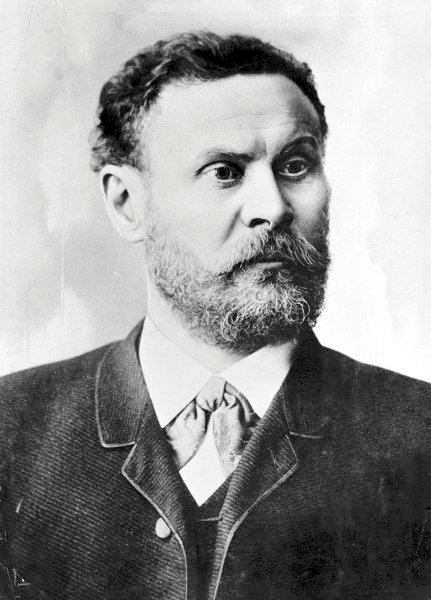
Sergei Pavlovich Korolev
Role: Rocket engineer and spacecraft designer
Born: January 12, 1907 Died: January 14, 1966
Best known for: Soviet space programme, R-7 booster rocket, Sputnik
Alma Mater: Odessa Building Trades School, Kiev Polytechnic Institute, Moscow State Technical University
Sergei Korolev was one of the key Soviet figures of the Space Race, but also one of the most secretive. The secrecy during the Cold War meant that Korolev was officially, even to cosmonauts of the time, only known as “Chief Designer” to protect him from US assassination attempts. Korolev was especially talented at mathematics at an early age, and after receiving vocational training in carpentry he used his skills to design a glider. During his university days as a student in aeronautical engineering in Kiev and Moscow he continued to built and fly gliders, suffering many injuries as a result, and ultimately obtaining his diploma under the tutelage of the famous aircraft designer Andrei Tupolev. After graduation, Korolev worked in many different engineering roles, piquing an interest in liquid-fueled rockets after working on the Tupolev TB-3 heavy bomber. In 1931, Korolev co-founded the Group for the Study of Reactive Motion (GIRD), which became one of the earliest state-sponsored centres for Soviet rocket research, launching the liquid-fueled rocket GIRD-X in 1933. In the same year, GIRD merged with the Gas Dynamics Laboratory to form the Jet Propulsion Research Institute (RNII), which focused particularly on rocket stability and control using automated gyroscopic stabilisation systems. In 1938, Korolev was imprisoned after being accused of deliberately slowing down the work of RNII and for mismanagement of research funds on unsuccessful rocket experiments. Korolev remained imprisoned for six years, on occasion tortured, sentenced to death, sent to a Siberian labour camp, and finally forced to work as a slave labourer on party leadership-designated science projects. Korolev was discharged from prison by a special government decree in 1944 and was reinstated in the Red Army in 1945, but by this time the Soviet Union had massively fallen behind Germany in rocket research. Based on Korolev’s work on rocket-assisted takeoff systems during his time as a prisoner, Korolev was sent to Germany after WWII to recover some of the V-2 rocket technology. Even though many of the leading rocket brass in Germany emigrated to the US under Operation Paperclip, the Soviets were able to use the expertise provided by more than 2000 engineers and designers that had worked as technicians in the production process of the V-2. After Stalin made rocket development a national priority, Korolev oversaw a team of around 200 German specialists at the new NII-88 institute on Gorodomyla Island, 200 km from Moscow. Korolev became chief designer of the the long-range missile section of the Special Design Bureau 1 of NII-88. His team created a replica V-2, known as the R-1 missile, which showed the same reliability issues as the V-2 in terms of target-hitting accuracy. The following design evolution doubled the range of the original V-2 (R-2 missile), and further increased the range to reach England (R-3 rocket). Korolev then joined the Communist Party in order to apply for government funds that would realise his rocketry ambitions. Under this programme, Korolev led the design of the first intercontinental ballistic missile (ICBM), the R-7 Semyorka, a two-stage rocket with sufficient power to carry a nuclear bomb for 7,000 km. Following the successes of the R-7, Korolev was fully rehabilitated by the Soviet government.
Korolev had already conceptualised ideas in 1953 about using an ICBM to shoot a vehicle into Earth’s orbit. Thus, he pitched the Soviet Academy of Sciences to fund a programme that would adapt the R-7 to shoot a dog into orbit. After the US media began publicly announcing its plans to develop satellites for geophysical purposes, Korolev realised the potential for a great upset if the Soviet Union became the first to realise this goal. Sputnik 1 was designed and constructed in under one month (ultimately a metal sphere with batteries powering a transmitter), and launched in October 1957 using an R-7 booster to international acclaim. The Sputnik 2 capsule was six times bigger than Sputnik 1, again rapidly designed and constructed in four weeks, and carried the dog Laika into space just a month later. As there was no mechanism for re-entry, Laika died during this mission. After these missions, Korolev turned his attention to reaching the Moon, and to do so, ordered the re-design of the upper-stage of the R-7 booster. After a failed Luna 1 mission (yet still the first to leave geocentric orbit), Luna 2 became the first space probe to impact the moon (1959), and just a month later Luna 3 became the first space probe to take a picture of the far side of the Moon. During this time and the subsequent attempts to send a man to the Moon, Korolev’s visions were hampered by the limited government funding available, which meant that launches had to be rushed with inadequate testing. Korolev’s planning for a moon landing began with the design of the Vostok manned spacecraft. A modified version of the R-7 booster rocket was again used to launch Yuri Gagarin into orbit in 1961, and later Valentina Tereshkova as the first woman cosmonaut in space on Vostok 6. After these successes, Korolev planned a new N1 rocket (based on a very unreliable NK-15 liquid-fuelled rocket engine) and the Soyuz spacecraft to carry crew to low-earth orbit and beyond, but Korolev’s unexpected death in 1966 greatly interrupted the practical implementation of his plans. Later critics have pointed out that Korolev’s chief asset was not his scientific or engineering prowess but rather his brilliant management capabilities and his ability to bootstrap components developed for different purposes into one working unit. Ultimately, this bootstrapping philosophy failed to work robustly for the more complex Moon landing endeavours.

Samuel Pierpont Langley
Role: Physicist, inventor and aviation pioneer
Born: August 22, 1834 Died: February 27, 1906
Best known for: “Almost” being the first to design a successful heavier-than-air aircraft.
Samuel Langley is best known for his work as an astrophysicist, professor of astronomy at a number of institutions, the third Secretary of the Smithsonian Institution, and the inventor of the bolometer (instrument used to measure infrared radiation and temperature used by Svante Arrhenius in 1896 to calculate the effects of CO2 on climate). But Langley is also known for his work on heavier-than-air aircraft for the Smithsonian Institution. After his nomination to secretary of the institution, Langley began experimenting with gliders and small models powered by rubber bands, repeating the experiments conducted by Alphonse Pénaud. He then built a “wind tunnel” (essentially a rotating propeller arm to which different objects could be attached) and tested larger aircraft models that were powered by small steam engines. Langley realised that heavier-than-air flight would be possible when he observed that a brass plate connected to his rotating arm could be held aloft by just a tiny connecting spring (the spring alone could not hold the brass plate up alone, so the difference must be provided by aerodynamic lift). On May 6, 1896 his Number 5 unpiloted model flew about 1 km after being launched by a catapult from a boat on the Potomac River in Washington, DC. This extended the contemporary record of heavier-than-air flight by about tenfold, and proved that sustained flight was possible with enough stability and sufficient lifting force. In the same year, his model Number 6 broke this record to 1.5 km, which landed Langley grants totalling $70,000 to develop functional piloted airplanes (Langley preferred the designation “Aerodrome”, roughly translated as “air runner” from Greek). Two engineers, Stephen Balzer and Charles Manly, designed a petrol engine to Langley’s power and weight specifications, but this engine probably had way too much power than was necessary for the job (the 50 bhp engine quadrupled the power output of the Wright brothers’ 12 bhp engine). The aerodrome itself featured wire-braced tandem wings, with a Pénaud-like tail for controlling pitch and yaw. Roll control surfaces were not installed on this aircraft, and Langley relied instead on passive roll stability using upwards-angled wings (dihedral angle). While the Wright brothers designed an aircraft that could be controlled in strong winds and land on solid ground, Langley preferred flight in calm air over the Potomac river, requiring the use of a catapult for launching, and splashing into the river to land (typically severely damaging the aircraft). Unfortunately for Langley, the two launches he attempted in 1903 crashed into the Potomac river. During the first flight, the aerodrome’s wings seemingly clipped the catapult and led to an instability, while on the second flight, the aerodrome fell apart after being launched from the catapult. After the national media and US Members of Congress ridiculed and criticised Langley for his work, he gave up on any further attempts. In 1914, Glenn Curtiss modified the aerodrome and flew it for a couple hundred feet. This feat was used by the Smithsonian Institution for a number of years to lay claim to “the first man-carrying aeroplane in the history of the world capable of sustained free flight”. However, the general consensus remains that the Wright brothers have due claim to this achievement, as only the Wright flyer had a mechanisms for stably controlling the airplane (roll, yaw, and pitch). Today, Langley’s name lives on through a number of awards (Langley Gold Medal), institutions (NASA Langley Research Centre) and the US’ first aircraft carrier (USS Langley).
Otto Lilienthal
Role: Early pioneer of aviation
Born: May 23, 1848 Died: August 10, 1896
Best known for: First well-documented and repeated flights with unpowered airplanes
Alma Mater: Royal Technical Academy in Berlin
As a young boy, fascinated by the prospect of flying, Otto Lilienthal began studying bird flight and built a set of (unsuccessful) strap-on wings with his brother. After graduating from a technical school and apprenticing for the Schwarzkopf company, he became a certified design engineer and started his own company, designing mining machines, boilers and steam engines. Soon Lilienthal turned most of his attention to his childhood passion of flying. Like Sir George Cayley before him, he studied the mechanics of birds in great detail and published his famous book “Birdflight as the Basis of Aviation” in 1889. This book summarised his research, especially on storks, using polar diagrams (sink rate vs airspeed) to describe the aerodynamics of bird wings. Based on his insights, he built and patented gliders fitted with a crossbar for carrying and flying the hang gliders (much like hang glider designs today). Between his first glider version of 1891, the Derwitzer, and his tragic death on 10 August 1896 after his glider stalled and crashed from a height of 15 m, Lilienthal made over 2,000 flights in gliders. In the beginning, these flights were merely little jumps from small hills covering distances of around 20 m, but he could also use small thermal updrafts to remain stationary and call to photographers to take fascinating pictures. In 1893, he set his personal record of flying 250 m, which remained unbeaten by anyone until his death. Lilienthal’s legacy lived on for many years as newspapers and magazines captured photographs of Lilienthal flying, which greatly influenced the public’s interest in flying developments and increased scientific experiments regarding the possibility of developing sustained flying machines. The Wright brothers credited Lilienthal as major inspiration for their decision to pursue manned flight in the first place:
“Of all the men who attacked the flying problem in the 19th century, Otto Lilienthal was easily the most important. … It is true that attempts at gliding had been made hundreds of years before him, and that in the nineteenth century, Cayley, Spencer, Wenham, Mouillard, and many others were reported to have made feeble attempts to glide, but their failures were so complete that nothing of value resulted.” — Wilbur Wright

Charles Augustus Lindbergh
Role: Aviator and author
Born: February 4, 1902 Died: August 26, 1974
Best known for: First solo transatlantic flight (1927)
Alma Mater: University of Wisconsin-Madison
Charles Lindbergh had a meteoric rise to fame, when in 1927 as a US Air Mail pilot, he won the Orteig Prize as the first Allied aviator to fly non-stop from New York City to Paris in 33 hours and 30 minutes. Several famous aviators had made unsuccessful attempts at the time, and six lives were lost in the process, before Lindbergh crossed the Atlantic in a custom-built, single-seat monoplane “The Spirit of St. Louis”. The Orteig Prize ($25,000 in 1927, $342,000 in 2015) spearheaded considerable investment in the aviation industry before it was finally won by Lindbergh. This investment totalled many times more than the value of the Prize itself, but upon Lindbergh’s achievement, the Prize significantly raised the public’s interest in aviation and led to advancements in airplane technology. Lindbergh himself devoted much time and effort in promoting commercial aviation after his achievement, publishing his autobiography soon after his prize-winning flight and touring the US on speaking events. Specifically, his autobiography “WE”, referring to the spiritual partnership he had developed with his airplane during the transatlantic flight, was highly influential in outlining Lindbergh’s enthusiasm for the future of aviation, selling 650,000 copies in the first year. He was also a promoter of the Air Mail service, his earlier vocation, by flying a special souvenir route of 3,000 self-addressed envelopes by US citizens between the Dominican Republic, Haiti and Cuba. However, Lindbergh also bore a much greater personal cost for his achievement, when due to his fame, his son Charles Jr. was kidnapped and murdered in what the American media called “The Crime of the Century”. Lindbergh was fundamentally a pacifist and an advocate of non-interventionism in the WWII battles between Nazi Germany and Britain, and resigned his commission in the US Air Force in 1941, when President Roosevelt criticised Lindbergh for his views (some believed Lindbergh to be a Nazi sympathiser, although this sentiment might have stemmed from his fear of “loot and barbarism” that the Soviet forces might unleash over Western Europe if Nazi Germany lost the war). After Pearl Harbour, Lindbergh renounced some of his views and supported the US’ active war effort, although he was not reinstated in the US Air Force during WWII. Lindbergh’s legacy also lives on in the Longines Lindbergh watch that he developed alongside the Longines watch company to make navigation easier for pilots. This watch first came to market in 1931 and is still being produced today. Lindbergh was also a patron to the rocket scientist Robert Goddard and helped him to secure a grant from Daniel Guggenheim in 1930. In later life, Lindbergh served as a consultant to the US Air Force and to Pan Am World Airways, and President Eisenhower commissioned Lindbergh as a brigadier general in the US Air Force Reserve.
This is the first post of a three-part series (see the second post here) on great engineers, inventors, pioneers, aviators and pilots that have shaped the history of aviation. Each profile provides a little nugget of information about their key achievements and invites you to learn more about these pioneering men and women by clicking on the embedded links. While this is not a comprehensive list, I have tried to include a broad spectrum of names, including the classics we have all heard of, as well as some of the less well known, and in my opinion, underrated pioneering aviators. Enjoy!

Edwin Eugene “Buzz” Aldrin
Role: Pioneering US Astronaut
Born: January 20, 1930
Best known for: Apollo 11 Moon landing
Alma Mater: US Military Academy (1951) and MIT (1963).
“Buzz” Aldrin flew 66 combat missions in the Korean War, and after serving as test pilot entered the space program. Aldrin first flew into space on November 11, 1966, performing a record-breaking 5 hour space walk on the Gemini 12 mission. He is best known for piloting the lunar module for the historic July 20, 1969 Apollo 11 landing on the Moon, and became the second person to walk the Moon, spending a total of 2 hrs and 30 min on the surface.
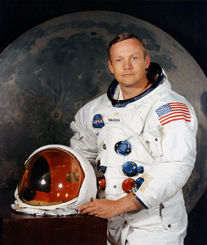
Neil Alden Armstrong
Role: Pioneering US Astronaut
Born: August 5, 1930 Died: August 25, 2012
Best known for: First man on the Moon
Alma Mater: Purdue University (1955), University of Southern California (1970)
Neil Armstrong flew 78 combat missions in the Korean war, before joining NASA in 1955 as a research test pilot. He flew the famous X-15 research plane to the edge of space (~200,000 feet altitude), which laid the groundwork for the space program. Armstrong was the command pilot on Gemini 8 in March 1966, which performed the first successful docking of two spacecraft. This mission was then aborted after Armstrong needed to use his reentry fuel to prevent a dangerous spin of the aircraft—the first space emergency. He is best known for his spacecraft commander role on the Apollo 11 mission to the Moon, on which he became the first man to walk on the Moon. His phrase “That’s one small step for a man, one giant leap for mankind“, suitably captured the gravity of this moment and provided the inspiration for many engineers to come.
.jpg)
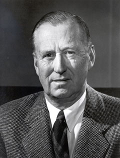
John Leland Atwood
Role: Aircraft Designer and Industrial Executive
Born: October 26, 1904 Died: March 5, 1999
Best known for: P-51 Mustang, F-100 fighter, X-15 rocket plane, Apollo program
Alma Mater: Hardin-Simmons University (1926) and University of Texas (1928)
Atwood was one of the heavyweights of the American aerospace industry for more than 40 years, and his career spanned arguably the most prolific period in aerospace engineering; from WWII fighter jets to the early beginnings of commercial flight and all the way through the space program. He started as a junior airplane designer in the Army Air Corps in 1928, and then moved to the Douglas Aircraft Company to work on the design of the DC-3 aircraft. After joining North American Aviation (NAA) in 1934 he quickly rose the ranks becoming assistant general manager (1938), vice president (1941) and was later elected as president (1948) and CEO (1960) of the company. Atwood has been called by many as the “chief engineer’s chief engineer” and he played a large role in turning NAA into the most prolific manufacturer of military aircraft to this day. At NAA, Atwood was one of the original designers of the agile P-51 Mustang, arguably one of the best designed fighter-bomber aircraft of WWII, featuring many new features such as low-drag laminar flow wing and new engine cooling arrangements, and remaining in service until the 1980s. Other aircraft designed by NAA under Atwood’s leadership include the T-6 Texan trainer, the B-25 Mitchell bomber, the F-86 Sabre jet used in the Korean War, the supersonic F-100 Super Sabre, the hypersonic X-15 and the XB-70 Valkyrie, one of the most advanced strategic bombers ever developed. After NAA merged with Rockwell Standard Co. in 1967, Atwood became the new president and CEO of Rockwell International, which produced many contributions to the space program such as the Apollo command and service modules, the second stage of the Saturn V lunar launch vehicle and the Rocketdyne F-1 and J-2 rocket engines of the Saturn V rocket. Even after retiring he continued to influence the design of the Space Shuttle and the Rockwell B-1 Lancer bomber.

Walter Beech
Role: Pioneering Aviator and Aircraft Designer
Born: January 30, 1891 Died: November 29, 1950
Best known for: Founder of Beech Aircraft Company with Olive Ann Beech
Walter Beech started early in his aviation career building a glider from a wrecked Curtiss biplane at the age of 14. Initially a US Army pilot during WWI, he soon joined the Swallow Airplane Company where he rose quickly from test pilot to general manager in 1924. Beech started the Travel Air Manufacturing Company with co-founders Clyde Cessna and Lloyd Stearman, and Travel Air Manufacturing became the world’s largest manufacturer of commercial mono- and biplanes. After Travel Air Manufacturing merged with the Curtiss-Wright Airplane Company, Beech started a new venture, the Beech Aircraft Company, with his wife Olive Ann Beech, in 1932. Many of their early designs were successful in aviation competitions (Bendix Trophy), setting new distance and speed records, and some, such as the Beechraft Model 17 Staggerwing Biplane (lower wing farther forward than upper wing to reduce wing interference), were years ahead of its time. During WWII, Beech focused entirely on defence, producing more than 7,000 military aircraft, which were widely used for training purposes. After WWII, Beech focused on new lightweight aircraft, which culminated in the “V”-tailed Beechcraft Bonanza of 1947, which is still being produced today and has been in production longer than any other airplane.

Louis Charles Joseph Blériot
Role: Pioneering Aviator
Born: July 1, 1872 Died: August 1, 1936
Best known for: Flight across the English Channel, first successful monoplane design
Alma Mater: Ecole Central Paris
Louis Blériot began his engineering career as a very profitable manufacturer of automobile headlamps, and used the proceeds of this business to build his first aircraft. Four years after the maiden flight of the Wright brothers, Blériot successfully flew the world’s first monoplane of his own design, the Blériot VII, in 1907. Blériot followed much of the same design process as the Wright brothers, learning to fly as he constructed his aircraft (canard configuration Blériot V and tandem-wing Blériot VI) and improving the design by trial and error. Blériot achieved world renown on July 25, 1909 by being the first to fly an aircraft across the English Channel in a heavier-than-air aircraft, his Blériot XI monoplane design. Although the flight from Les Barraques, France to Dover, England was only 22 miles across the open sea, the quickly changing weather conditions over the English Channel and poor reliability of aircraft at the time, highlighted his skill as a pilot and aircraft manufacturer. The gravity of this event is not be understated as it was the second big appraisal of aviation after the Wright brothers’ maiden flight. The English newspaper The Daily Express headlined their coverage of the event with “England is no longer an island”! During WWI, Blériot’s company Blériot Aéronautique and its associated venture Société Pour L’Aviation et ses Dérivés built the SPAD biplane fighters, one of the most successful fighters during the war, and flown by all of Allied Nations, and until his death, Blériot remained a paragon of aeronautical science and sport aviation.

William Edward Boeing
Role: Aircraft Manufacturer
Born: October 1, 1881 Died: September 28, 1956
Best known for: Founder of Boeing Airplane Co.
Alma Mater: Sheffield Scientific School, Yale University (1903)
Like many aviators of the time, Boeing developed an interest in aviation as a hobby. After leaving Yale before graduating, Boeing initially worked in the lumber business in the Pacific Northwest, acquiring a considerable amount of land and shipping lumber to the East Coast via the Panama Canal. While learning to fly in 1909 at the Glenn L. Martin Flying School in Los Angeles, he became convinced of the superiority of aircraft as a future means of transportation, and purchased one of Martin’s planes. When this plane crashed, and replacement parts would not be available for months, Boeing and his friend George Conrad Westervelt, decided to build their own plane. Together, Boeing and Westervelt incorporated the Pacific Aero Products Corporation and built the Boeing Model 1. Only a month later, when the USA entered WWI, Boeing changed the name to the Boeing Airplane Company, the forerunner of today’s industrial giant. Initial government contracts for the new company included 50 trainer airplanes for the Navy and 200 pursuit planes for the Army Air Services. At the end of the war, Boeing started flying air mail services between Vancouver, BC and Seattle, which started the commercial operations of the Boeing business. By the end of the 1930s, the Boeing Company was already one of the largest U.S. aircraft manufacturers, and was also flying passengers across the country on regular schedules, which eventually morphed into United Airlines. For this dual accomplishment of manufacturing and transportation, Boeing was awarded the prestigious Daniel Guggenheim Medal in 1934.

Karel Jan Bossart
Role: Rocket Scientist
Born: February 9, 1904 Died: August 3, 1975
Best known for: Atlas ICBM
Alma Mater: Université libre de Buxelles (1924)
Karel Bossart must be considered as one of the leading rocket scientists and designers of all time, but because most of his work was conducted for the US Air Force, it remains classified and relatively little known. Even to this day, Bossart stands in the shadow of his contemporate, Wernher von Braun (see next entry), even though Bossart’s rocket designs were by no means inferior. After graduating with a degree in Mining Engineering in Belgium, Bossart won a scholarship to MIT to study aeronautical engineering, and then worked in the USA for the rest of his life. In 1945, as chief structural engineer at Convair, he proposed a missile with an 8000 km range which could replace the strategic bombers which had been operating so successfully (or detrimentally) during WWII. The US Air Force was originally sceptical of his proposal but granted him a small limited contract, which was then mothballed in 1947, and revived in 1951 as the Cold War began to escalate and it became clear that the Soviets were progressing with their own ICBM program. Bossart’s rockets, which became to be known as the Atlas series, used an internally pressurised monocoque shell design, a novel fuel system, gimbaled engines for directional control, and a separable nose cone. Ultimately, the Atlas never became effective as an ICBM but proved to be one of the most reliable launch vehicles during the space race, especially the USA’s first manned spaceflight program, Project Mercury. The Atlas rocket was also used to launch the first communications satellite, the first US manned orbital mission, to launch the Mariner probes to Mars and Venus, and the Pioneer 10 and 11 probes to Jupiter and Saturn.

Wernher von Braun
Role: Rocket Scientist
Born: March 23, 1912 Died: June 16, 1977
Best known for: V-2 missile, Redstone rocket and Saturn V rocket
Alma Mater: Technical University of Berlin (1924)
Wernher von Braun is one of the best known figures of rocket development in Nazi Germany, and one of the fathers of rocket technology and space science in the USA. Indeed, von Braun had one of the best mentors you could think of—Professor Hermann Oberth. Oberth was one of the founding fathers of rocketry, whose doctoral dissertation on rocket science in 1922 had been rejected as too “utopian”, but it was indeed one of the first documents to use formal scientific principles to the idea of building spaceships. It was this space pioneer that Wernher von Braun assisted during his doctoral studies at the Technical University of Berlin, and to whom he later accredited with much of his success as a rocket engineer. Upon graduating, von Braun initially worked on rocket development with the German Ordinance Department, which managed to launch a series of liquid-fueled rockets known as the Aggregat rockets. The successful launch of the inertial-guided A-3 rocket in 1937 led to the founding of the rocket centre at Peenemünde, where during WWII, von Braun redesigned the A-3 into the A-4 variant, more famously known as the long-range V-2 ballistic missile. Shortly after the development of the A-4 rocket, von Braun was promoted to full Professor, an exceptional status for anyone at the age of 31!
After WWII, von Braun’s scientific credentials earned him special immigration status to the USA under Operation Paperclip, alongside the V-2 technology, and he further developed the V-2 at White Sands Proving Ground, New Mexico. In 1950, von Braun and his team were moved to Huntsville, Alabama to develop the Redstone rocket, a direct descendant of the V-2 and dubbed the “Army’s Workhorse” because it was used for the first live nuclear ballistic missile tests and was also used to launch the first American astronaut, Alan Shepard, into sub-orbit in 1961. After Redstone, von Braun was promoted to director of the Development Operations Division in Huntsville, Alabama (1956), and he and his team designed the Jupiter-C rocket. This rocket launched the West’s first satellite, the Explorer 1, into orbit in 1958, officially signalling the USA’s entry into the Space Race. In 1960, von Braun’s team moved again to the newly created NASA Marshall Flight Test Centre in Huntsville, where von Braun became the centre’s first director. Again under von Braun’s leadership, his team developed the mighty Saturn rockets that launched Buzz Aldrin, Neil Armstrong and Co (see above). to the Moon. In 1970, von Braun became Deputy Associate Administrator at NASA headquarters and was awarded the National Medal of Science in 1975.

Louis Charles Breguet
Role: Aviation Pioneer and Industrialist
Born: January 2, 1880 Died: May 4, 1955
Best known for: Breguet range equation, Breguet 14 and 19, Air France
Louis Breguet was one of the first aviation pioneers that attempted to place the construction of aircraft on a more rigorous scientific footing. This was no surprise given that Breguet was born into a family with a keen interest and tradition in engineering and science (he was the grandson of the famous horologist Abraham-Louis Breguet). In 1905, Breguet built his own version of a laboratory wind tunnel, which he used to study the effects of different airflows on wings and started to built a gyroplane (forerunner of the helicopter) under the guidance of Charles Richet. In 1907, Breguet’s gyroplane achieved the first flight of a vertical-flight aircraft, even though only to a height of 2 ft. Breguet was one of the first to appreciate that experimentation and testing during the design and manufacturing phase is critical for reliability. Indeed, his first biplane, the Breguet Type 1, built in 1909 proved to be of high quality with outstanding performance characteristics, setting multiple speed records but also defining the accepted quality standards for many years to come. As was the case for many early aviation pioneers, WWI proved to be a litmus test. The companies that received Army contracts survived, and the others largely fail by the wayside. Breguet’s company produced around 7,800 Breguet 14 reconnaissance aircraft for the Allied war effort, and helped to establish airplanes as a new military weapon. The Breguet 14 was one of the first aircraft to use metal construction, in this case aluminium structural members, making the airframe lighter than a wooden one for the same strength. This imparted the Breguet 14 with superior agility and speed, but the metal construction also helped the aircraft to sustain more damage. After the War, the Breguet 19 became famous for flying long distances over land and sea, and on the back of this reputation, Breguet established the Compagnie des messageries aériennes in 1919, which today has morphed into Air France.

Sir Sydney Camm
Role: Aircraft Designer
Born: August 5, 1893 Died: March 12, 1966
Best known for: Hawker Hurricane, Hawker Hunter and Hawker Siddeley P.1127
Sydney Camm is one of the most famous British airplane designers of the WWII and post-WWII periods. He is best remembered for this work for the Hawker Company, especially on the Hawker Hurricane fighter, which bore the brunt of the German onslaught during the Battle of Britain, and the first vertical takeoff and landing aircraft, the Hawker Siddeley P.1127. Camm and his brothers developed an early interest in aviation, building model airplanes and selling them to the students at nearby Eton College. In 1923, Camm joined the Hawker Aircraft Company (later Hawker Siddeley) as a draughtsman, but the success of his first design, the Cygnet, led to his quick promotion to chief designer in 1925. Camm’s legacy is manifest in the fact that he is responsible for 52 different aircraft designs, of which 26,000 were manufactured, and at one point 84% of the RAF aircraft in service were Camm designs! Camm was a difficult man to work for, ridiculing engineers that made foolish mistakes. Crucially for innovation, however, he rarely scolded designers for new design or manufacturing ideas, and had no respect for engineers without new ideas or indeterminate solutions. His WWII designs, the Hawker Hurricane, Hawker Typhoon and Hawker Tempest, are now iconic classics. Camm understood incredibly well how to incorporate jet engines, which were blossoming after WWII, into streamlined and agile aircraft designs. His most significant design after WWII is probably the Hawker Hunter which proved to be one of the most successful military aircraft ever designed. His final crowning achievement is the P.1127, which was the forerunner of the Hawker Siddeley Harrier. The Harrier is well known for its vertical takeoff and landing capabilities which required a synthesis of many new technologies such as vectored thrust engines and reaction control systems.

Sir George Cayley
Role: Flight Scientist and Engineer
Born: December 27, 1773 Died: December 15, 1857
Best known for: First successful human glider, established the four aerodynamic forces, invented the basis for modern aircraft design
Even though Leonardo da Vinci is known for his early theoretical sketches about flying machines, Sir George Cayley must be considered as the true founding father and first scientific aerial investigator. Cayley is one of the most important people in the history of aviation, as he was the first person to understand the underlying principles of flight. Cayley was a genius who studied all aspects of flight in a rigorous scientific manner—dissecting bird wings, testing different airfoils, devising and testing his theories about flight, and ultimately building his own gliders. He maintained a meticulous record of all of his experiments, which then proved invaluable for the next generation of aviation pioneers. In 1799 he published the concept underlying any modern aircraft as a fixed-wing machine with separate mechanisms for lift, propulsion, control. By observing birds flying he correctly inferred that cambered (arched) wing profiles were a means of providing lift, and that flying could be controlled by wing twisting. Cayley flew model gliders based on these insights, and later developed full scale versions to be flown as kites. Sometime around 1848, Cayley cajoled a little boy to sit in a glider, who consequently became the first person in history to fly. In 1853, Cayley launched a glider off his rooftop, with supposedly, one of his employees (coachman or butler) as a passenger. A true polymath, Cayley worked on all aspects of flight, establishing key insights about the relationship of wing area, camber and lift; highlighting the four basic aerodynamic forces lift, drag, weight and thrust; developing means to determine the centre of pressure of an airfoil; highlighting the superiority of streamlined (teardrop) shapes and the need for vertical and horizontal tail planes for flight stability; developing the concept of wheels as an undercarriage; designing wire-braced biplane structures to carry loads; and correctly predicting that sustained flight would not be possible until a lightweight engine was developed to provide the necessary thrust. Essentially, Cayley single-handedly figured out or highlighted the key principles of flying machines, and all aviation pioneers and engineers to come, inevitably stand on his shoulders.

Clyde Vernon Cessna
Role: Aircraft Designer and Industrialist
Born: December 5, 1879 Died: November 20, 1954
Best known for: Cessna Aircraft Corporation
Clyde Cessna found his passion for aviation at the relatively mature age of 31 (1910), while attending an aerial exhibition in Kansas. For the rest of his life, Cessna dedicated himself to aviation, designing and constructing his own lightweight aircraft and becoming a competent pilot. His first design of 1911, a monoplane nicknamed the “Silverwing”, was constructed from linen and spruce and can be considered as a variant of the Bleriot XI from France. Cessna crashed this airplane 12 times, until he finally managed to get it off the ground, completing a 5-mile flight to return back at his initial point of departure. In 1925, he founded the Travel Air Manufacturing Company alongside Walter Beech and Lloyd Stearman, and with Cessna as its president, the company became one of the leading U.S. aircraft manufacturers, producing a line of internationally famous aircraft that set speed and distance records. After disputes with his partners over the merits of monoplane versus biplane design, Cessna left the company to form his own company, the Cessna Aircraft Corporation. Even though Cessna designed successful aircraft such as the Cessna AW, CW-6, DC-6 and the CR-series of aircraft that set world speed records, the Great Depression caused a dramatic drop in sales, ultimately leading to a bankruptcy filing and the complete closure of the company by 1931. In 1934, Cessna re-opened the business but soon sold his interest to his cousins, Dwane and Dwight Wallace, who would turn the business into a global success. To this day, Cessna aircraft are the predominant training aircraft that are used to introduce the pleasure of flying to many people around the globe.

Octave Alexandre Chanute
Role: Aviation Historian and Experimentalist
Born: February 18, 1832 Died: November 23, 1910
Best known for: His book “Progress in Flying Machines”
Octave Chanute was a self-taught engineer that began his first career in railroad construction at the Hudson River Railroad. Over the years, he became especially known for his novel designs and complex constructions of railroad bridges (e.g. Hannibal bridge) and terminals. Chanute also invented a method for pressure-treating wooden railroad ties with antiseptic to prolong their service life. At the age of 51, instead of retiring, Chanute started his second career in aviation. His first step was to assemble a massive compendium of all known data on the science of flight up to this point, in order to highlight shortcomings and publicise the successes and failures of pioneers. This publication, Progress in Flying Machines, was the first synthesis of the history of flight and therefore earns him the title of first aviation historian. Chanute also became a close friend and advisor of many experimentalists and pioneers of the time, such as Lilienthal, Bleriot, and the Wright brothers, with whom he struck up an especially close relationship. At the same time, Chanute conducted gliding experiments throughout the 1890s, filling some of the holes in the available data on aircraft stability and the strength of materials. His close familiarity with box structures in bridge construction, naturally led him to design the classic strut and wire-braced biplane construction, widely used until Hugo Junkers all-metal cantilever monoplane design without external bracing introduced during WWI. Chanute shared his knowledge freely with everyone that asked, and he expected others to do exactly the same. This approach led to some friction with the Wright brothers later on with regard to their attempts to patent the Wright Flyer based on the concept of wing warping for steering and stability.
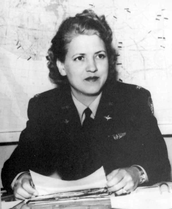
Jacqueline Cochran
Role: Aviation Pioneer and Racing Pilot
Born: May 11, 1906 Died: August 9, 1980
Best known for: Women’s Auxiliary Army Corps, Women Airforce Service Pilots, record-setting pilot
After a friend offered Jacqueline Cochran a ride in his airplane, she became enthused with flying in her twenties and learned to fly in a mere three weeks. Soon she started to fly solo and to enter in speed flying competitions. In 1937, she was the only woman to enter the prestigious Bendix Trophy, and after winning the Bendix in 1938 and setting transcontinental speed and altitude records, she became known as one of the best pilots in the US and the undisputed “Speed Queen”. Cochran also became the first woman to fly a bomber across the Atlantic, win five Harmon Trophies (awarded to the year’s most outstanding aviator/aviatrix), and at the time of her death held more speed, distance and altitude records than anyone else in history. In aviation history, Cochran is however best known for her public service and initiative in creating the Women Airforce Service Pilots (WASP) during WWII, envisioning female pilots to help in domestic and noncombat aviation jobs, in order to free more male pilots for combat service. As director of WASP, Cochran was responsible for training female pilots, and for this wartime service she received the Distinguished Service Medal in 1945.

Claude Honoré Désiré Dornier
Role: Aircraft Designer and Industrialist
Born: May 14, 1884 Died: December 5, 1969
Best known for: Dornier Do X flying boat and all-metal monocoque construction
Alma mater: Technical University of Munich (1907)
After graduating from the Technical University of Munich in 1907, Dornier first worked as a structural engineer at Nagel Engineering Works. In 1910, he joined the famous Luftschiffbau Zeppelin company, where he was quickly recognised by Ferdinand von Zeppelin himself for his outstanding technical abilities. He was appointed von Zeppellin’s personal scientific advisor, and in this role began to improve the design of lightweight metal sections. As such, he is directly responsible for the first all-metal stressed skin (monocoque) aircraft designs, such as the biplane cantilever-wing Zeppelin-Lindau D.I, which was the first aircraft of this type to go into production. Unable to fully convince the Zeppelin officials of the merits of diversification into aircraft, in 1914 he set-up his own aircraft company with his brother, the Dornier Flugzeugwerke. After WWI, the Treaty of Versailles forbade any construction of aircraft in Germany, such that foreign companies, such as CMASA and Piaggio in Italy, license-built Dornier designs. In the 1920s, Dornier designed the largest, heaviest and most powerful flying boat of the time, the Do X, which set a new record in the number of passengers carried (150), unbroken for 20 years, and flew from Germany to New York in 1930. During WWII, the Luftwaffe used the Dornier Do 17 and Do 217 as bomber and reconnaissance aircraft. Dornier also developed the fastest piston-engined fighter of WWII, the Do 335, which was introduced too late to enter combat. Following WWII, the Dornier business was not allowed to produce any more airplanes, so that Dornier moved to Switzerland, where he consulted in aeronautical engineering.
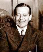
Donald Wills Douglas
Role: Aerospace Engineer and Industrialist
Born: April 6, 1892 Died: February 1, 1981
Best known for: Douglas Aircraft Company, DC-3 passenger plane
Alma mater: MIT (1914)
Donald Douglas was the first official aeronautical student at MIT. He started his professional career at the Glenn L. Martin Company. Alongside David Davis he built the Cloudster biplane, which became the only product of the Davis-Douglas Company, and which had been designed to make the first non-stop flight across the US. Even though the plane failed to achieve this feat, it was the first aircraft to lift more payload than it’s own dry mass. Following this failure, Davis lost interest and Douglas founded his own firm in California in 1921, the Douglas Aircraft Company. Douglas led the design and production of the first airplanes to circumnavigate the globe, and Douglas Aircraft produced a number of civil and military aircraft, most notably, the advanced passenger plane, the DC-1. Under Douglas’s leadership, the Douglas Aircraft Company became of the leaders in the commercial aircraft industry, and fought a multi-decade struggle for supremacy with the Boeing company. The now legendary DC-3 airliner, and its popular military derivative the C-47 Skytrain of WWII, established Douglas Aircraft as the temporary winner in this competition. However, with the continuing series of planes, the DC-4, DC-6, DC-7 and the DC-8 and DC-10 jets, Douglas started to fall behind, but nevertheless can take the credit for introducing aviation to the first generation of jet-setting customers.

Hugh Latimer Dryden
Role: Aeronautical Scientist and Cicil Servant
Born: July 2, 1898 Died: December 2, 1965
Best known for: NASA Deputy Director
Alma mater: Johns Hopkins University (1916, 1919)
Hugh Dryden was awarded a M.S. and a PhD in physics from Johns Hopkins University. He completed his PhD while working at the National Bureau of Standards at the age of 20, the youngest ever to receive a PhD from Johns Hopkins. Upon this achievement, he was appointed the director of the newly founded Aerodynamics Division at the National Bureau of Standards. His long research career in aerospace engineering led to significant advancements in our understanding of boundary layer phenomena. His studies on airfoils near the speed of sound and the phenomenon of turbulence, contributed to the design of the P-51 Mustang, and directly influenced the design of supersonic jets and missile technology. During WWII, he was the chief consultant to the U.S. Air Force, and after WWII he directly influenced the Air Force’s research goals. After WWII, Dryden became the Director of the National Advisory Committee on Aeronautics (NACA), and served as a Science Advisor to the President. After NACA morphed into NASA, Dryden became the Deputy Director, and under his leadership role, the US space program was launched with Project Mercury.
If you enjoyed this post, why not check out the second post in the series? Read on here.
The technological jump from no functional aeroplane to the first serious military fighter occurred in a mere 10 years. The Wright brothers conducted their first flight in late 1903 and by 1914 WWI broke out with an associated expansion in military flying. This expansion occurred almost entirely without the benefits of organised science in formal institutions and universities, and was led predominantly by tinkering aviators. Aircraft pioneers were often gifted flying-buffs or sporting daredevils, but very few of them had any real theoretical knowledge. This proved to be sufficient for the early developments, when flying was mostly a matter of strapping a powerful and lightweight engine to a basic flying design, and having the skills to keep the aircraft aloft and stable. Many pioneers, like Charles Rolls, paid with their lives for this mindset and it took many accidents from stalls and spins to figure out that something was amiss.
The specifications and operating environment of aeroplanes was, of course, entirely different from either cars or trains. Particularly the design requirements for reliable yet lightweight construction posed a conundrum for early aerospace engineers. To make something stronger, a rule of thumb is to add more material. For aircraft this means increasing the wall-thickness of the beams, frames and plates that comprise the aircraft. Of course, by making components thicker, the structure becomes heavier and less likely to fly. Furthermore, thicker structures are stiffer, which causes loads to be redirected within the structure, and rather counter-intuitively, can make the aircraft more likely to fail.
This counter-intuitive finding was played-out during the discovery of wing twisting. Wings are predominantly subject to bending forces due to aerodynamic lift that keeps the aircraft aloft. As this is entirely obvious, and since there was a great deal of acquired expertise in bridge building, wing bending loads were supported quite reliably by beams (spars) running along the length of the wing. The wing is, however, also subject to large twisting forces, and if these are not accounted for, the wing will twist-off the fuselage.
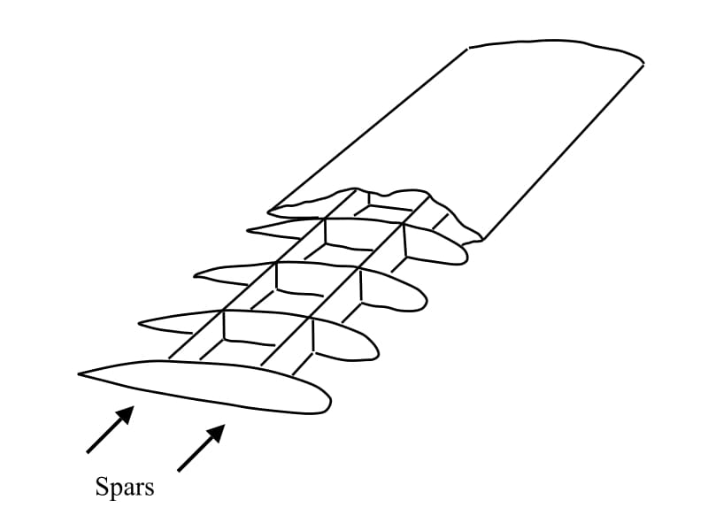
Spars running along the length of the wing and connected by a series of ribs
By 1917, the Allies had developed a certain degree of air superiority over the Western Front of WWI by means of better biplane construction. Out of necessity the Dutch engineer Anthony Fokker, working in Germany at the time, was developing a more advanced monoplane design with performance specifications better than anything the Allies had to offer. While biplanes are very light and were the preferred type of construction up to that point, their flying performance in terms of nimbleness and speed is limited due to the high drag induced by the aerodynamic interference of the two separate wings. There was thus a strong incentive to build faster monoplane aeroplanes. But since the fateful crash of Samuel Langley into the Potomac River in 1903, monoplanes had the reputation of being entirely unreliable.
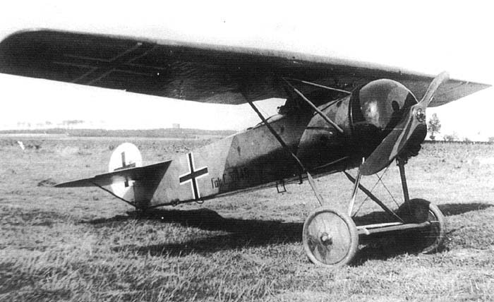
Fokker D8
And indeed, as soon as Fokker’s new D8 aeroplane flew in combat situations, the wings started to snap-off as pilots pulled out of dives during dogfights. Being pressed for time, the D8 hadn’t gone through an extensive series of flying tests, and this cost many of Germany’s best pilots their lives. As a result, the German Air Force ordered a series of structural tests on the D8. As in the more standard biplanes of the time, the wings of the D8 were entirely covered by a thin fabric whose only purpose was to provide an aerodynamic profile for lift creation. The fabric itself did not carry any of the aerodynamic loads, and indeed all wing-bending loads were carried by two spars projecting from the fuselage and running along the length of the wing. The spars were connected by a series of ribs which served as attachment points for the stretched fabric. According to the testing standards of the time, the D8 aircraft was mounted upside down with weights suspended from the wings to simulate aerodynamic loads six times the weight of the aircraft. When tested this way, the wings showed absolutely no sign of weakness. When increasing the load beyond the factor of six, the wings began to fail in the aft spar such that the German authorities ordered all rear spars to be replaced by thicker and stronger ones. Unfortunately for the German military command, the accidents of the D8 become more frequent as a result of this intervention. Germany’s engineers now faced the perplexing conundrum that adding more material to the wings seemingly made them weaker!
At this point Fokker took matters into his own hands and repeated the tests in his own factory. What he found was that not only would the wings rise as a result of aerodynamic loads, but they would twist too, even though there was no obvious twisting loads being applied. Particularly important was the direction of twisting, which occurred as to twist the leading edge upwards, thereby increasing the angle of attack and the lift created by the wings, thus further increasing wing twisting, and so on in a detrimental feedback loop. As a pilot pulled up out of a dive, the extra lift needed to pull-off the manoeuvre was sufficient to initiate this catastrophic feedback loop, until the wings eventually twisted-off. Fokker had discovered the phenomenon now known as “divergence”.
But why did this divergent behaviour occur in the first place?
Imagine two horizontal and identical beams placed side by side and connected by a number ribs along their length to bridge the gap between them. One end of this assemblage is free and the other is rigidly supported (clamped). This simple construction is basically the fundamental structure of even the most modern aircraft. If a vertical load is applied exactly halfway between the two beams at the free end, then both beams will just bend upwards without any twist. However, if the vertical load is biased towards one of the beams then the assemblage will bend and twist at the same time, because the load carried by one beam is greater than the load carried by the other. The point where a load must be applied such that a structure bends without twisting is known as the flexural centre.
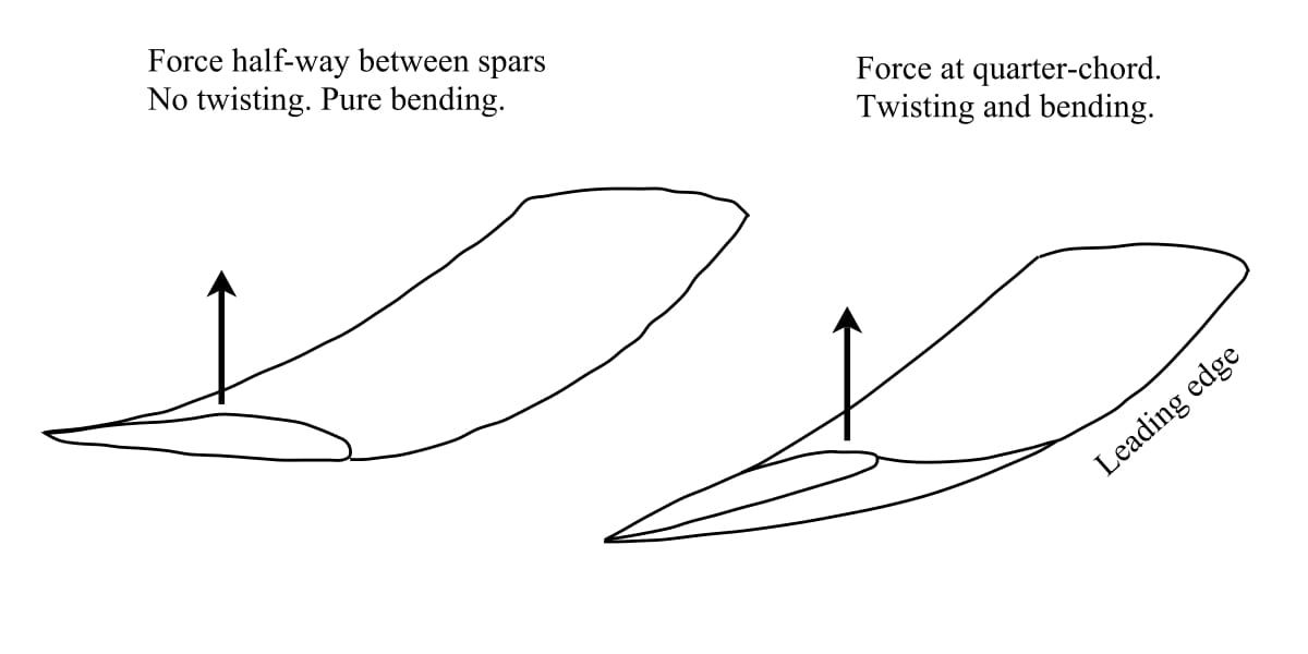
If a load is applied at the flexural centre (for a wing pretty much half-way between the two spars) the wing will only bend. But because the centre of pressure is located at the quarter-chord position, the wing bends and twists at the same time. The load is not applied at the flexural centre
Of course, if there are more than two beams or if the beams are of different stiffness, then the flexural centre will not be halfway between the beams. In fact, the aerodynamic lift forces are distributed across the wing and do not really act at a single point. However, the distribution of aerodynamic pressure can be summed up and represented mathematically as acting as a point load somewhere between the front and rear spars. This point is known as the centre of pressure and may shift along the length of the wing. One might assume that the centre of pressure of a wing profile is situated nicely in the middle of the two spars, but this is not what happens. The centre of pressure for most wing profiles is in fact just behind the front spar, in the vicinity of the quarter-chord position, that is 25% of the chord length behind the leading edge. Therefore it follows quite simply that if the flexural centre and centre of pressure do not coincide, the wing must twist and bend at the same time. The extent of twisting naturally depends on this mismatch and the stiffness of construction in torsion. It is the designer’s role to minimise it as much as possible, and in fact, the thick quill of a bird’s feather is located at about the quarter span to minimise twisting.
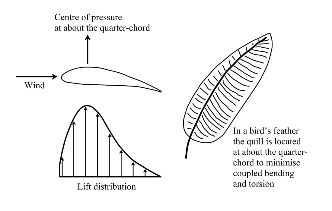
Wing lift distribution with centre of pressure at the quarter-chord. A feather features a reinforcing “spar” at the quarter-chord to prevent twisting of the feathers
In the simple fabric-covered D8 monoplane, the flexural centre and torsional stiffness of the wing depended entirely on the two wing spars. In early designs of the D8, the centre of flexure was pretty much bang in the middle between the two spars, and the fruitless attempts of beefing-up the rear spar only moved the flexural centre further to the rear and away from the centre of pressure at the quarter chord. So Fokker decided to reduce the thickness of the rear spar, thereby not only solving the problem of divergence but also making the aircraft lighter and a serious menace to the British and French biplanes.
Fokker also came up with a second design evolution that enabled monoplanes. In the early fabric-covered monoplanes the torsional stiffness of the wing is provided entirely by differential bending of the two spars. Not much can be done to improve the torsional stiffness by tinkering with the design of these spars. This was part of the reason why monoplanes were forbidden in the early days of flying. It was a safety precaution, and not a particularly unpopular one, because in practise many biplanes were not much slower than monoplanes and considerably more reliable.
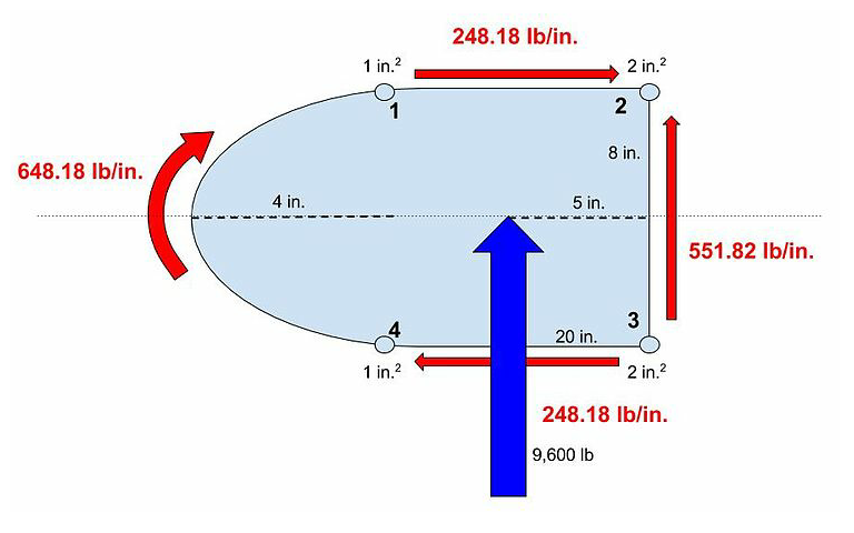
An example of the shear flow around a wing box due to a vertically applied load
As a structure is sheared it creates what is called shear flow – the shearing force divided by the length of material over which it acts. Because the fabric does not carry sufficient loading, the early fabric-covered monoplane construction is considered an “open” cross-section as shear cannot flow from one spar to the other. The strutted and braced construction of the biplane, however, has the advantage of creating a closed “torsion box”. The torsion box of biplanes creates a closed cross-section and the shearing forces can flow around the material to optimally resist torsion. Torsion is therefore ideally resisted by any box or tube whose sides are continuous. The second breakthrough of monoplane construction was therefore to replace the fabric with thicker sheet-metal that could carry load. Now the closed aerodynamic surface of the wing could provide the job of resisting shear loads efficiently, while the two spars predominantly served to resist bending loads. In effect, this is an efficient division of labour concept even though it requires a much thicker and heavier wing to resist torsion.
References
[1] J.E. Gordon. Structures: Or Why Things Don’t Fall Down. DeCapo Press. 2nd Edition, 2003.
This post is a first. Up to now, all content on this blog has been exclusively written by myself. But recently Nick Mehlig and Ben Names from Structural Design and Analysis, Inc. (SDA), a team of stress engineers that design lightweight and load efficient structures, contacted me with a proposal for a guest post. The reason why I agreed is because the guys at SDA have a unique perspective on a fascinating real-world engineering problem — re-designing the wing of a Fokker D-VII. The Fokker D-VII was a German fighter aircraft in World War I but was also used by many other countries after the Great War. This post is a look at some of the details of how aircraft components are designed.
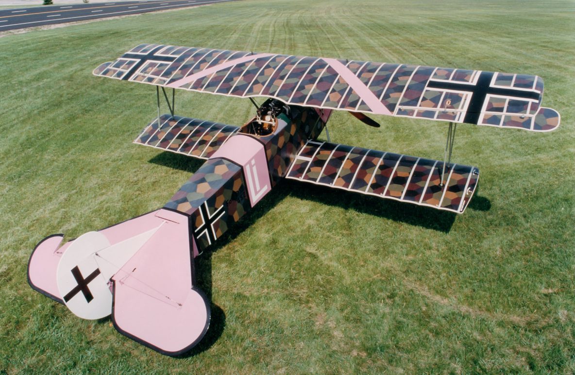
Within the Aerospace Engineering community, there is an entire sub-discipline devoted to understanding the dynamics of a system and how loads are generated (propulsive, inertial, aerodynamic, etc). In smaller companies, engineers often need to wear multiple hats, and the lines between classical stress analysis and aerodynamic loads analysis begin to blur. Recently, Structural Design and Analysis, Inc. (SDA) worked with a local resident who had taken it upon himself to build a Fokker D-VII Biplane from scratch, and wanted to know how much weight he could save if he used an aluminium spar for the main wings instead of the original wooden spar design.
Our engineers had to develop a finite element model (FEM) and conduct the basic loads and dynamics analysis to define the load cases for the vehicle. Generating aerodynamic loads is relatively straight forward for aircraft with more conventional designs. Typically, a combination of 2D aerodynamic theory and corrections for wings with finite span are used to generate the loads in the early stages of the design phase. These loads are then applied to the structure at the quarter chord location of the wing. For the Fokker, this analysis is slightly more complicated because the biplane construction creates interference effects between the upper and lower wing which must be considered when determining the loads that act on the aircraft.

The goal of this case study is to show that various approaches can be taken to solve this loads-generation problem, and that the “best” approach for an engineer depends on his/her technical expertise, available resources (time and/or money), and the desired accuracy of the results. Three different methods were selected to calculate the aerodynamic loading on the Fokker D-VII biplane, and they are listed in increasing order of required technical expertise and accuracy:
- Assuming that each wing can be analysed separately. This type of solution is best suited to an aircraft enthusiast or an engineer without much background in theoretical aerodynamics.
- Accounting for the interaction between the upper and lower wing using correction factors. This type of solution is best suited for an engineer with a level of understanding comparable to an undergraduate education in aerospace engineering.
- Using an advanced FEM analyses suite such as NX Nastran’s Static Aeroelastic SOL 144. This solution technique requires the least amount of effort on the user since the loads are calculated internally by NX Nastran, but is best suited to an engineer with some postgraduate education in aerospace engineering.
Let’s compares the efficacy of these three methods and the accuracy of their respective results.
Method 1
The first step in calculating the aerodynamic loads on the aircraft is to get the airfoil data. The Fokker D-VII uses a modified Goettigen GOE 418 airfoil for the upper wing. The airfoil data points (see the diagram below) were imported into XFOIL, a popular open-source 2D potential flow code, and the lift coefficients were extracted for various angles of attack (AOA). Using the XFOIL data, a plot relating the wing’s AOA to the lift coefficient (


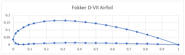
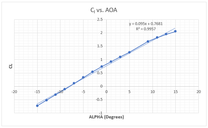
To calculate the lift on the upper and lower wings, a simple approximation from Prandtl Lifting Line Theory is used which relates the 3D lift coefficient to the 2D lift curve slope, the wing aspect ratio (AR) and the AOA. The lower wing of the Fokker D-VII has a 


The lift equation was then used to calculate the lifting force on the wings.


where 


To balance the aircraft, the moment created by the wing lift about the centre of gravity of the Fokker needs to be balanced by the tail wing lift force, 


The sum of these three loads is 


These final loads are applied to the quarter chord location of the wings. Here, a rectangular spanwise lift distribution is applied to the upper and lower wings.
Method 2
By having two wings subject to the same flow, each wing interacts with the other’s vortex system such that the upper wing experiences an increase in lift and the lower wing experiences a decrease in lift, denoted by 


Where 

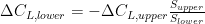
The methods of finding the values of 


Plugging in values for 


Using the new corrected values for the wing coefficients 


Again, the loads are applied to the quarter-chord position of the aircraft wings. Two different spanwise lift distributions are applied to the model for this comparison study. The first assumes an elliptical lift distribution. The second uses Schrenk’s Approximation to estimate a more accurate spanwise lift distribution. These two distributions are shown below along with a reference to a rectangular distribution.
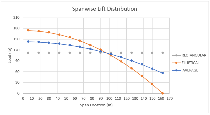
Method 3
The third and final method is to use NX Nastran’s static aeroelastic SOL 144 analysis to generate the loads using a vortex lattice formulation. A potential flow model is created in FEMAP to generate the aerodynamic loading for the Fokker. One of the powerful functionalities about SOL 144 trim analysis is that given high-level information about any flight condition, Nastran cannot only calculate the aerodynamic forces, but can also ensure that the vehicle is stable. With just a few clicks, the load case can be modified to model any corner of the flight envelope by changing the dynamic pressure and load factor of the aircraft. Since Nastran calculates all the loads internally using this high-level flight condition information, it can save an incredible amount of time that might be devoted to calculating loads externally, bringing them in, and applying them to the structure accurately. This solution requires the least amount of effort on the user since the loads are calculated internally by NX Nastran and then applied to the FEM through the points defined in the model. NX Nastran automatically calculates the trim condition of the aircraft and calculates the loading on the upper wing, lower wing, and horizontal tail. The resulting loads are shown below:


Results
As the complexity increases with each of the methods discussed above, so does the accuracy of the results. However, not every stage of the design requires the same precision. Since this discussion focuses on how the analysis approach impacts the design of the aircraft, let us first compare the calculated loads for all three methods. Below is a table outlining the loads for each method and the percentage difference when compared to the aeroelasticity finite element model (the most accurate loads generation approach).
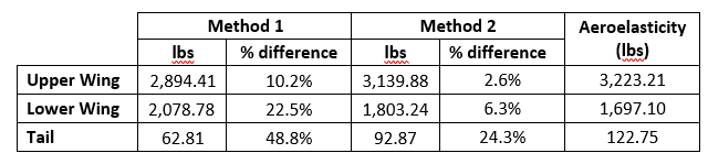
When comparing the lifting force of upper and lower wings of the aircraft, the aerodynamic loading from method 1 underestimates the lift on the upper wing by 10.2% and over estimates the lift on the lower wing by 22.5%. Applying Simple Biplane Theory in method 2 captures the interference effects and estimates the wing loading much more accurately with the upper wing lift only 2.6% less and the lower wing lift 6.3% greater, when compared to the aeroelastic model. A more detailed way to compare the resulting design impact of the three different load generation methods is to look at the internal shear and bending moment diagrams within the spars. Below is the shear force diagram for the upper wing leading edge spar.
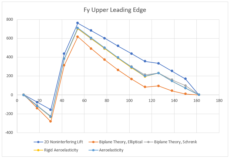
Starting with the simplest method, the 2D non-interfering lift generates the highest shear force. As one would expect the variation in the maximum internal shear force is small (at most 7% difference) over all the models since the total lift generated by the plane was set to be constant. The differences are partially due to how the lift is distributed between the upper and lower wings. Furthermore, the spanwise distribution clearly has an impact on the internal shear force. Interestingly, the model that matches the shear force of the aeroelasticity model the closest is the Biplane Theory model using Schrenk’s approximation. The differences produced by these aerodynamic models becomes even more apparent when inspecting the internal bending moment.
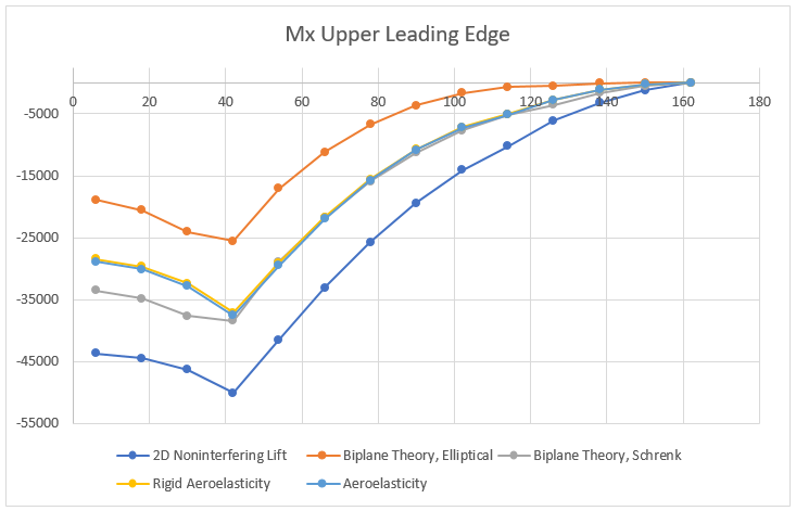
The internal bending moment clearly shows how differences in the aerodynamic models can propagate. The most basic model (2D Non-interfering Lift) produces the highest bending moment, 33% higher than the aeroelastic solution. While it is safer to be on the conservative side, this kind of inaccuracy will lead to a substantially heavier structure, thus limiting performance.
The shear and bending moment diagrams are often excellent indicators of the internal stress state within simple structures. As a stress engineer, comparing stress plots is the most meaningful way to compare how the different aerodynamics models impact the stress throughout the vehicle. Below is a picture of the upper wing leading and trailing edge spars Von Mises stress under a 4g pull up when using the aeroelasticity model.
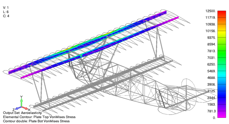
The max spar cap Von Mises stress is 11.4 ksi. In comparison, the same stress contour is presented below, only for the case using the Biplane theory using Schrenk’s approximation, which exhibited a maximum Von Mises stress of 11.5 ksi, a 0.8% difference from the aeroelastic aerodynamic model.
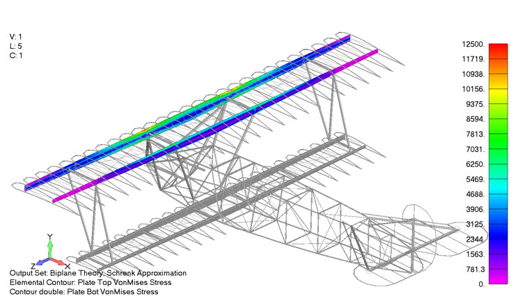
In contrast, the Von Mises stress state for the upper wing under the 2D non-interfering lift can be seen below as a gross overprediction, predicting a maximum Von Mises stress of 15.2 ksi, 33% higher than the aeroelastic aerodynamic model.
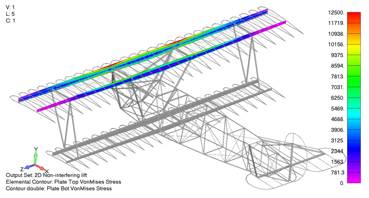
Conclusion
Having exhaustively explored the impact of different aerodynamic models on the final stress results, several conclusions have become clear. First and foremost, as laid out at the beginning, none of these approaches are inherently bad. However their mileage does vary significantly. Requiring the least technical background, the 2D non-interfering lift model provides a good approximation of the stress state in the leading and trailing edges, but is over-conservative in predicting internal stresses. As expected, including the interference effects between the upper and lower wing in the simple Biplane Theory and applying finite span effects has the potential to predict stresses within 0.8% of the most accurate model. Unfortunately, this relies on the user correctly calculating the span wise loading and interference effects which often requires complex analytical methods or using a potential flow method. Furthermore, there are ample opportunities for an engineer to make a mistake when taking this approach, and it could be difficult to detect these without the results of a more accurate model to compare to.
Now, given that fairly accurate stress distributions using semi-analytical methods can be achieved, you might be asking yourself, why might anyone want to spend the money to use the NX Nastran Aeroelasticity module? First, it removes substantial uncertainty in the accuracy of the aerodynamic model. The Nastran Aeroelasticity module can account for interfering lifting surfaces, slender fuselage effects, ground effect, compressibility, wing sweep and taper, as well as a number of other factors. Additionally, once implemented, the Nastran Aeroelasticity module is more flexible than generating the loads from an outside source and then applying those loads within FEMAP (the pre/post environment). Nastran can generate the loads for any flight condition such as steady level flight, a 4g pull up, or a 3g coordinated turn, requiring only high level information from the user.
Finally, the user is also provided with additional information such as the trim angle of attack, control surface deflection angles, and vehicle stability derivatives. As with most problems, there is rarely a single correct approach, but when high accuracy and case-generation flexibility are desired, then using NX Nastran’s Static Aeroelastic Solution 144 is the way to go. However, if you are working on a budget, can take on additional mass, or do not have the technical background to employ Solution 144, then using an analytical method or generating the loads some other way externally is probably the way to go.
References
[1] Diehl, W. S., “Relative Loading on Biplane Wings,” NACA TR-458, January 1934
A very important parameter when designing jet engines is specific power – the amount of power output divided by the mass of the engine. In general, a good heuristic to keep in mind when designing anything that moves is that maximising the power output per unit mass leads to a more efficient design. Afterburning is an exception to this rule. Yes, afterburning provides more thrust and therefore provides more bang for every gram of jet engine, but it is terribly fuel inefficient.
Afterburning, sometimes also called reheat, is a means of increasing the thrust of a jet engine in order to improve aircraft take-off and climb performance, to accelerate beyond the sound barrier, or in a military setting, for improved combat performance. Of course, we could simply increase the thrust by building a bigger and more powerful engine, but this naturally leads to a greater frontal area that impedes the oncoming flow, and therefore increases drag. Even though afterburning is incredibly fuel-inefficient, it is the best solution for enabling massive amounts of additional thrust at the switch of a button. This means an engine can be run in two modes – a fuel efficient, low thrust configuration and a fuel-inefficient, high-thrust configuration.
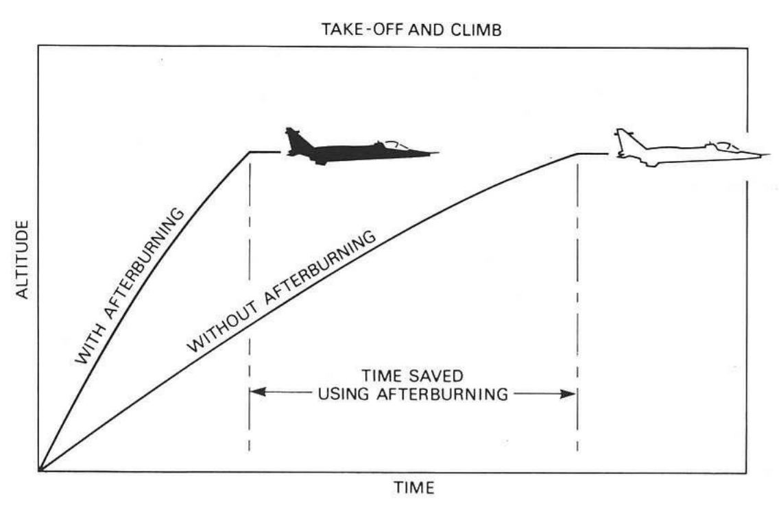
Effect of afterburning during take-off and climbing [1]
 , and the difference between the entry and exit velocities of air into,
  , and out of,
  , the jet engine.
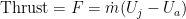
For a fixed airspeed 

and the rate of change in kinetic energy is
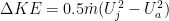
such that the propulsive efficiency is

This means that for a fixed airspeed
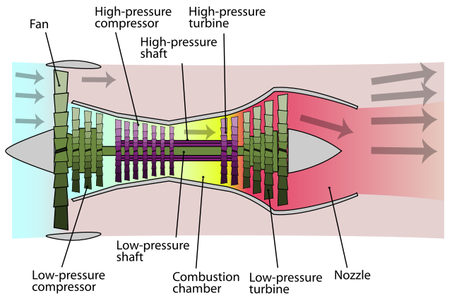
Schematic Diagram of Turbofan Engine (Photo credit: Wikipedia)
High bypass-ratio turbofan engines, which are the most common in modern airliners, are designed around this second principle – the big fan at the front sucks in tons of air, but because this flow bypasses the combustion chamber, it is not accelerated to a high exit velocity. The advantages of this design is that increasing the bypass ratio yields better fuel efficiency which means that turbofans can be operated over long periods (great for long-haul commercial passenger flights).
The downside, of course, is increased size and induced drag, which is a nightmare for nimble fighter aircraft. In fighter aircraft you want a small and compact engine that provides tons of thrust. Fuel efficiency is typically of secondary concern. Therefore, an afterburner naturally addresses the first principle we discussed above – accelerating the exhaust gases to higher velocity. This generally means that we can shrink the size of the engine and decrease the bypass ratio to provide better aerodynamic performance.
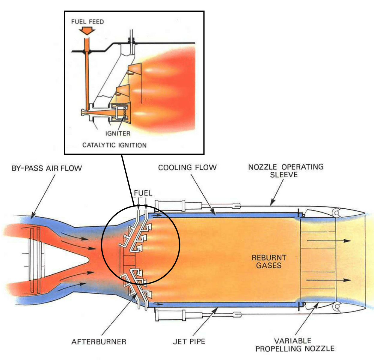
Schematic of afterburning components and functionality at the tail end of a jet engine [1]
The hot jet from the turbine flows into the jet pipe at a velocity of around 250 m/s to 400 m/s, and this velocity is far too high to guarantee stable combustion in the jet pipe. Just prior to the jet pipe, the cross-sectional area of the exit portion to the turbine increases to diffuse the flow to lower velocities. However, because the standard injection rate of kerosene at a good fuel-to-oxygen mixture is only around 1-2 m/s, the kerosene would be rapidly blown away even by the diffused jet stream. To prevent this a vapour gutter is placed just prior to the fuel injection nozzles that spins the jet into turbulent eddie currents, thereby further slowing down the hot turbine exhaust gases and allowing for a better mixture of fuel and jet stream. A common misconception is that due to the high temperature of the gases exiting the turbine (around 700°C), the fuel-oxygen mixture in the jet pipe would combust spontaneously. Cooler combustion flames can develop at these temperatures, but because of the atmospheric pressure differences between ground level and altitude, a design that spontaneously combusts at ground level would never do so at altitude. To guarantee a stable and smooth reaction over a wide range of mixture ratios and flying altitudes, a high-intensity spark is needed.
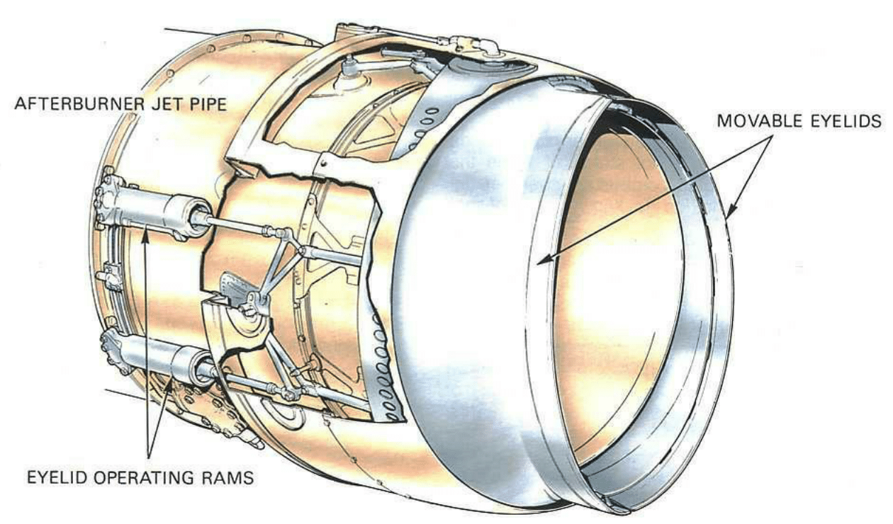
Two-position nozzle [1]
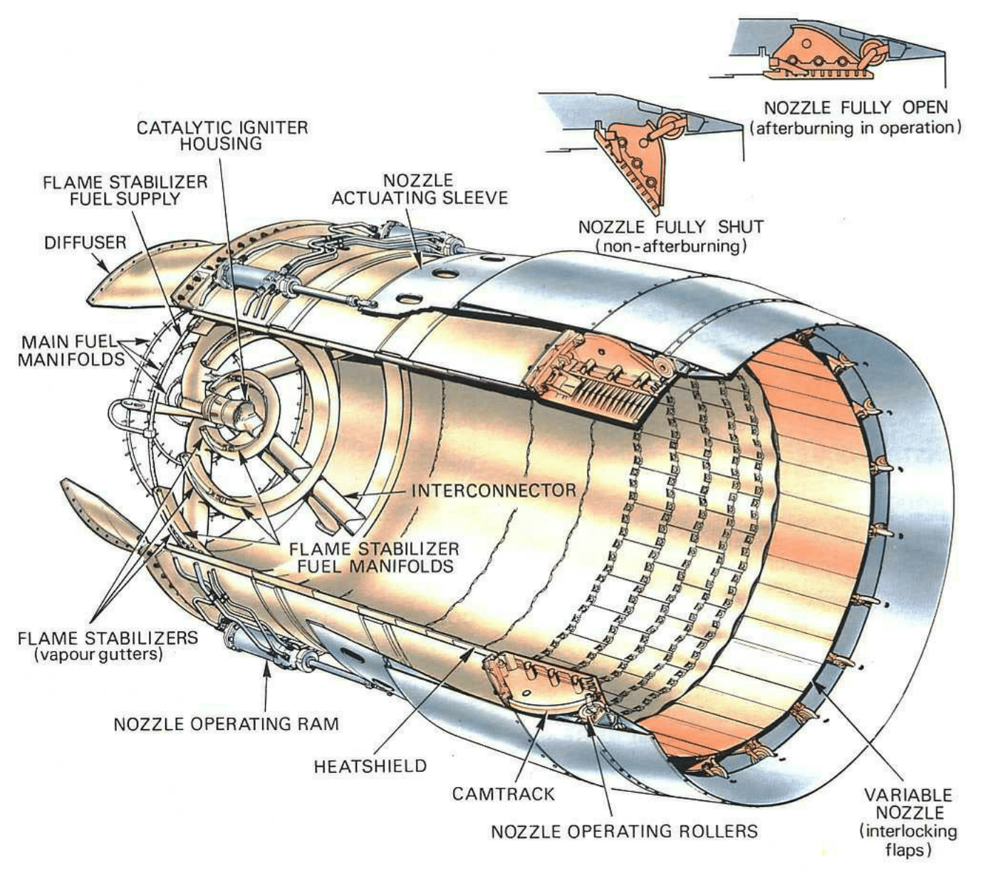
Variable-area nozzle [1]
Thrust and fuel consumption
The increase in thrust is a function of the increase in jet pipe temperature as a result of afterburning. For a perfectly efficient system, the relationship between the temperature ratio before and after fuel is burnt, and the thrust increase is nearly linear in the typical operating range with temperature ratios of 1.4 to 2.2. Within this range we can expect a 40% increase in thrust for a doubling of the temperature in the jet pipe. Thus, if afterburning raises the jet pipe temperature from 700°C (973 K) to 1500°C (1773 K) this results in a thrust increase of around 36%.
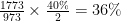
In a static test bed, thrust increases of up to 70% can be obtained at the top end, and at high forward speeds, several times this can be achieved. The lower the temperature exiting the turbine and the greater the extent of uncombusted oxygen, the greater the temperature increase in the jet pipe due to afterburning.
As is to be expected, afterburning naturally incurs a fuel consumption penalty, and this is why afterburning is typically constrained to short bursts. The aim of the compressor in a classic jet engine is to raise the pressure of the incoming air to the optimal pressure for efficient combustion. After expansion by the turbine stage, the gases are at a lower degree of compression, and therefore the fuel is not burnt as efficiently as in the combustion chamber between compressor and turbine. For a 70% increase in thrust the fuel consumption can easily double, but of course this increased fuel consumption is balanced by an improved performance in terms of take-off and climb. This means that the increased fuel consumption is balanced by the time saved to cover a desired distance or operating manoeuvre.
If you are interested in jet engine design, check out my posts on its history, compressor and turbine design, jet engine optimisation and turbine cooling.
References
The inspiration of this post and the diagrams have all been taken or inspired by [1] Rolls-Royce (1996). The Jet Engine. Rolls Royce Technical Publications; 5th ed. edition (Amazon link). For anyone interested in jet engine design this is a beautiful book, describing lots of intricate details about jet engine design and presenting the information in an intuitive and visually pleasing manner using diagrams as used throughout this post. I can not recommend this book enough.
Aeroelasticity is the study of the interactions between dynamic, inertial and aerodynamic forces that arise when a body is immersed in airflow. The unique challenge of aeroelasticity is to analyse how vibrations, static deflections and lift and drag forces combine, and to make sure that any interaction of these three forces does not lead to inferior aircraft performance or even failure.
The triangle in the figure below is known as Collar’s triangle and each vertex shows one of the forces mentioned above. When all three forces interact simultaneously we are in the realm of aeroelasticity and common failure modes include wing flutter and buffeting. When inertial and elastic forces combine in the absence of aerodynamic forces we are in the classical domain of structural dynamics and essentially dealing with any sort of mechanical vibration that you would experience on any piece of moving machinery. The interaction of inertial forces and aerodynamic forces gives rise to aerodynamic stability problems. How does an aircraft react to small disturbances – do the oscillations dampen out or do they get worse over time? Finally, the interaction of aerodynamic forces and elastic forces can give rise to a phenomenon known as divergence, which is an effect where twisting of the wing becomes theoretically infinite and can cause wings to twist off.

The Collar Triangle defining aeroelasticity as “the study of the mutual interaction that takes place within the triangle of the inertial, elastic, and aerodynamic forces acting on structural members exposed to an airstream, and the influence of this study on design.”
The two most dramatic aeroelastic effects are flutter and divergence. Flutter is a dynamic instability, often of the wing, caused by positive feedback between the wing’s deflection and the aerodynamic lift and drag forces. The flutter speed is the airspeed at which the wing, or any other part of the structure, starts to undergo simple harmonic motion – much like the simple to and fro motion of a simple pendulum – and this vibration occurs with zero net damping. Zero net damping means that there is no dissipation of energy (think of a pendulum swinging for eternity) and so any further decrease in net damping will result in self-oscillation – the structure is basically forcing itself to vibrate more and more, which at some point, will naturally lead to failure.
As we all know, the lift force acting on a wing will tend to bend it upwards, but what is less well-known is that this lift force can also cause the wing to twist. This is because the centre of pressure, the point where the total sum of the lift pressure field is assumed to act on an airfoil, is not necessarily coincident with the shear centre, the point through which a bending load needs to be applied to get pure bending without any twisting. Imagine holding a ruler in one hand and pushing up on it with your other hand. If you apply the load along the central axis of the ruler, the ruler will only bend, but if you apply the load at one of the two sides you can see the ruler bend and twist ever so slightly. Most of the time, the shear centre of an airfoil is not coincident with the centre of pressure, and so a lift force produces both bending and twisting. A critical phenomenon called divergence can occur when this twisting of a wing increases the angle of attack, which consequently increases the lift force further or creates further mismatch between shear centre and centre of pressure, so that a feedback loop ensues until the wing diverges or essentially shears off. In fact, one of the Wright Brothers’ main rivals in the race to being the first at heavier-than-air flight was Samuel Langley, whose prototype plane crashed into the Potomac river in Washington D.C., and this is now believed to have occurred as a results of torsional divergence. Furthermore, torsional divergence was a large problem with many WWI fighter planes and required a lot of additional stiffening of the wings.
Forward-swept wings
One of the domains where divergence is particularly pernicious is in forward-swept wings. Simply put, wing sweep delays the onset of shock waves over the wings and therefore reduces the associated rise in aerodynamic drag caused by boundary layer separation. In slightly more detail, as air flows over a curved object, such as an aircraft wing, it accelerates due to centripetal forces and this means that an aircraft travelling slightly slower than Mach 1.0 (the speed of sound) can develop pockets of supersonic flow over areas with high local curvature, typically the wings or the canopy. For thermodynamic reasons, supersonic flows terminate in a shock wave which results in a sudden increase in the density of the air. This effect disturbs the smooth flow over the wing and creates vortices behind the aircraft, which means it is a form of parasitic drag. Sweeping the wing reduces the curvature of the body as seen from the airflow by the cosine of the angle of sweep. For example, a 45 degree sweep reduces the effective curvature by around 70% (
Another way to think about the effect of sweep is to imagine the airflow over the wing as shown in the figure below. The effect of sweeping is such as to break the airflow into a component normal to the wing chord (“normal component”), and one along the span of the wing (“spanwise component”). The maximum curvature of the wing occurs along the wing chord, and the normal velocity component for the swept wing (


The figure above highlights another critical aspect of swept wings: the spanwise component. On a backward-swept wing the spanwise flow is outwards and towards the tip, while on a forward-swept wing it is inwards towards the root (see the figure below). Firstly, with the air flowing inwards towards the fuselage, wingtip vortices and the accompanying drag are reduced. Wingtip vortices form when the higher pressure air underneath the wing is sucked up onto the lower pressure top surface of the wing, thereby reducing the effective lift-generating surface of the wing. On most modern backward-swept airliners, winglets and sharklets prevent this phenomenon from occurring. Forward-swept wings similarly minimise this effect by re-routing some of the flow towards the wing root, and therefore allow for a smaller wing at the same lift performance. The second advantage of forward-swept wings is that shockwaves tend to develop first at the root of the wing, rather than towards the tips, and this helps to reduce tip stall. Aerodynamic control surfaces such as ailerons are typically located near the tips of the wings, because the further outboard, the greater their effect on controlling the rolling action of the plane. Tip stall essentially renders these ailerons useless, and therefore jeopardises the pilot’s control over the aircraft. As a result, the dangerous tip stall condition of a backward-swept design becomes a safer and more controllable root stall on a forward-swept design, providing better manoeuvrability at high angles of attack.

For all their merits, forward-swept wings suffer from one detrimental flaw – divergence. In a forward-swept wing configuration, the aerodynamic lift causes a twisting force that rotates the leading edge upward, causing a higher angle of attack, which in turn increases lift, and twists the wing further. With conventional metallic construction, additional torsional stiffening is typically required which adds weight, and is therefore sub-optimal in terms of aircraft performance.
Enter the Grumman X-29
The Grumman X-29 was an experimental aircraft developed by Grumman in the 1980’s, and flown by NASA and the US Air Force. The X-29 tested a forward-swept wing, canard control surfaces, and computerised fly-by-wire control to counter balance the various aerodynamic instabilities created by its airframe. From my perspective, the most important innovation, however, was the novel use of composite materials to control the aeroelastic divergence of forward-swept wings. At the time, composite materials were popular in the high-performance aircraft community as a means of creating stiff and strong structures at very low weight. In fact, composites were mainly used to save weight. However, the X-29 showcased a second advantage of this new material over classic metallic structures – multi-functionality.

Metals are isotropic materials, meaning that their stiffness is the same in all directions. The relationship between stress and strain along one direction of an aluminium panel is the same as in any other direction. Because composite materials are a union of stiff fibres held together by a resin matrix, we can manufacture panels that are stiffer in one direction than in another. This is because the composite material will be very stiff along the fibre direction but relatively compliant perpendicular to the fibre direction. In most fibre-reinforced composite materials, such as fibreglass and carbon fibre, this variation in stiffness is restricted to the plane of a single sheet of material known as an orthotropic lamina.
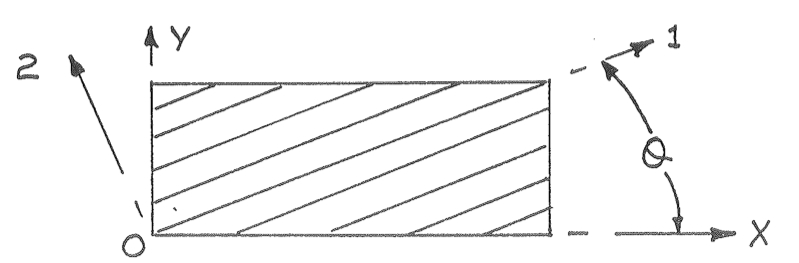
Consider one such layer of a continuous fibre-reinforced composite in the figure above. The material axes 1-2 denote the stiffer fibre in the 1-direction and the weaker resin in the 2-direction. If we align the fibres with the global x-axis and apply a load in the x-direction, the layer will stretch along the fibres and compress in the resin direction (or vice versa). However, if the fibres are aligned at an angle to the x-direction (of say 45°), and a load is applied in the x-direction, then the layer will not only stretch in the x-direction and compress in the y-direction but also shear. This is because the layer will stretch less in the fibre direction than in the resin direction. This effect can be precluded if the number of +45° layers is balanced by an equal amount of -45° layers stacked on top of each other to form a laminate, e.g. a [45,-45,-45,45] laminate. However, this [45,-45,-45,45] laminate will exhibit bend-twist coupling because the 45° layers are placed further away from the mid plane than the the -45° layers. The bending stiffness of a layer is a factor of the layer-thickness cubed plus the distance from the axis of bending (here the mid-plane) squared. Thus, even if the +45° and -45° layers have the same thickness, the outer 45° layers contribute more to the bending stiffness of the [45,-45,-45,45] laminate than the -45° layers do. Therefore, stretching-shearing coupling is eliminated in a [45,-45,-45,45] laminate as the number of +45° and -45° layers is the same, but bend-twist coupling will occur because the +45° layers are further from the mid-plane than the -45° layers.
Let’s now apply this effect at a wing level, i.e. a ![[+\theta,-\theta]](https://s0.wp.com/latex.php?latex=%5B%2B%5Ctheta%2C-%5Ctheta%5D&bg=ffffff&fg=000&s=0&c=20201002)
![[-\theta,+\theta]](https://s0.wp.com/latex.php?latex=%5B-%5Ctheta%2C%2B%5Ctheta%5D&bg=ffffff&fg=000&s=0&c=20201002)


In the Grumman X-29, this bend-twist coupling was successfully exploited to prevent divergence in the forward-swept wings. As aerodynamic lift forces the wing tips to bend upward, the forward-swept wing wants to twist to higher angles of attack, but the inherent bend-twist coupling of the composite laminates forces the wing to twist in the opposite direction and thereby counters an increase in the angle of attack – divergence is avoided!
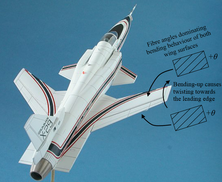
Bend-twist coupling in Grumman X-29 wings. Both top and bottom wing skin may have the same number of +theta and -theta fibre angles, but if the +theta angles are further from the wing mid-plane then they will dominate the bending behaviour and cause the leading edge to twist down as the wing bends up.
The Grumman X-29 is an excellent example of an efficient, autonomous and passively activated control system. Rather than adding more material to the wing to make it stiffer (but also heavier) an alternative solution is to use the bend-twist coupling capability of composite laminates. This capability is an example of elastic tailoring, and remains one of the most under-exploited advantages of composite materials. As the big aircraft manufacturers overcome the initial hurdles of using composites on a large scale with the 787 Dreamliner and A350-XWB, expect more and more of these multi-functional capabilities of composites to find their way onto aircraft components.
