In previous posts I have discussed the unique characteristics and manufacturing processes of a certain type of composite material, namely continuous fibre-reinforced plastics (FRPs). Just like many other composite materials, FRPs combine two or more materials whose combined properties are superior (in a practical engineering sense) to the properties of the constituent materials on their own. What distinguishes FRPs from other composites such as short-fibre composites, nanocomposites or discrete particle composites are the highly aligned, long bundles of fibres typically glass or carbon that are arranged in a specific direction within some resin system.
The biggest advantage of FRPs compared to metals is not necessarily their greater specific strength and stiffness (i.e. strength/density and stiffness/density) but the increased design freedom to tailor the structural behaviour. Metals and ceramics, being isotropic materials, behave in an intuitive way since the majority of the coupling terms in the stiffness tensor vanish. If you a imagine a three-dimensional cube and pull two opposing faces apart then the other two pairs of opposing faces will move towards each other. This phenomenon of coupling between tension and compression is known as the Poisson’s effect and aptly captured by the Poisson’s ratio.
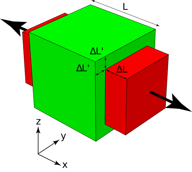
The Poisson’s effect in action
In bending, a similar phenomenon occurs known as anti-clastic curvature. If you have ever tried bending a thin, beam-like structure made out of a soft material e.g. a rubber eraser, you might have noticed that the beam wants to develop opposite curvature in the transverse direction to the main bending axis. The structure morphs into some form of saddle shape as shown in the figure. The phenomenon occurs because the bending moment applied by the person in the picture causes tension in the top surface and compression in the bottom surface in the direction of applied bending. From the Poisson’s effect we know that this induces compression in the top surface and tension in the bottom surface in the transverse direction. By analogy, this is exactly the reverse of the bending moment applied by the hands and so the panel bends in the opposite sense in the transverse direction.
Anticlastic curvature in action (1)
For isotropic materials the fundamental linear constitutive equations between stress and strain eliminate a lot of the possible coupling behaviour. There is no coupling between applied bending moments and twisting. No coupling between stretching/compressing and bending/twisting. And also no coupling between stretching/compressing and shearing. FRPs, being orthotropic materials, i.e. having two orthogonal axes of different material properties, can display all of these effects. Consider a single layer of a continuous fibre-reinforced composite in the figure below. The material axes 1-2 denote the stiffer fibre in the 1-direction and the weaker resin in the 2-direction. If we align the fibres with the global x-axis and apply a load in the x-direction, the layer will stretch/compress along the fibres and compress/stretch in the resin direction in the same way as described previously for isotropic materials. However, if the fibres are aligned at an angle to the x-direction say 45°, and a load is applied in the x-direction then the layer will not only stretch/compress in the x-direction and compress/stretch in the y-direction but also shear. This is because the layer will stretch/compress less in the fibre direction than in the resin direction. This effect can be precluded if the number of +45° layers is balanced by an equal amount of -45° layers stacked on top of each other to form a laminate, e.g. a [45,-45,-45,45] laminate. However, this [45,-45,-45,45] laminate will exhibit bend-twist coupling because the 45° layers are placed further away from the mid plane than the the -45° layers. The bending stiffness of a layer is a factor of the layer thickness cubed and the distance from the axis of bending (here the mid plane) squared. Thus, the outer 45° layers contribute more to the bending stiffness of the laminate than the -45° layers such that the coupling effects do not cancel.
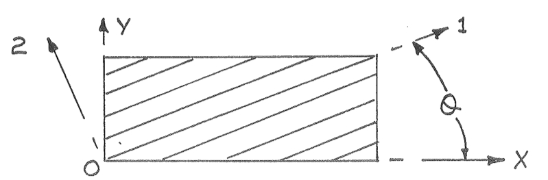
A single fibre reinforced plastic layer with material and global coordinate systems
Using metals, structural designers were constrained to tailoring the shape of a structure to optimise its performance i.e. thickness, length and width, and overall profile/shape. FRPs however add an extra dimension for optimisation by allowing designers to tailor the properties through the thickness and thereby achieve all kinds of interesting effects. For example, forward-swept wings on aircraft have and still are a nightmare due to aeroelastic instabilities like flutter and divergence. Basically, sweeping a wing forward is a neat idea because the airflow over swept wings flows spanwise towards the end furthest to the rear of the plane. Therefore, the tip-stall condition characteristic of backward-swept wings is moved towards the fuselage where it can be controlled more effectively. The drawback is that as the lift force bends the wingtip upwards the angle of attack increases, further increasing the lift and thereby causing more bending, and so on until the wings snap off or fail. Rather than adding more material to the wing to make it stiffer (but also heavier) an alternative solution is to use the bend-twist coupling capability of composite laminates. This was successfully achieved in the iconic Grumman X-29. As the bending loads force the wing tips to bend upward and twist the wing to higher angles of attack, the inherent bend-twist coupling of the composite laminate used forces the wing to twist in the opposite direction and thereby counters an increase in the angle of attack. This is an excellent example of an efficient, autonomous and passively activated control system to prevent divergence failure.
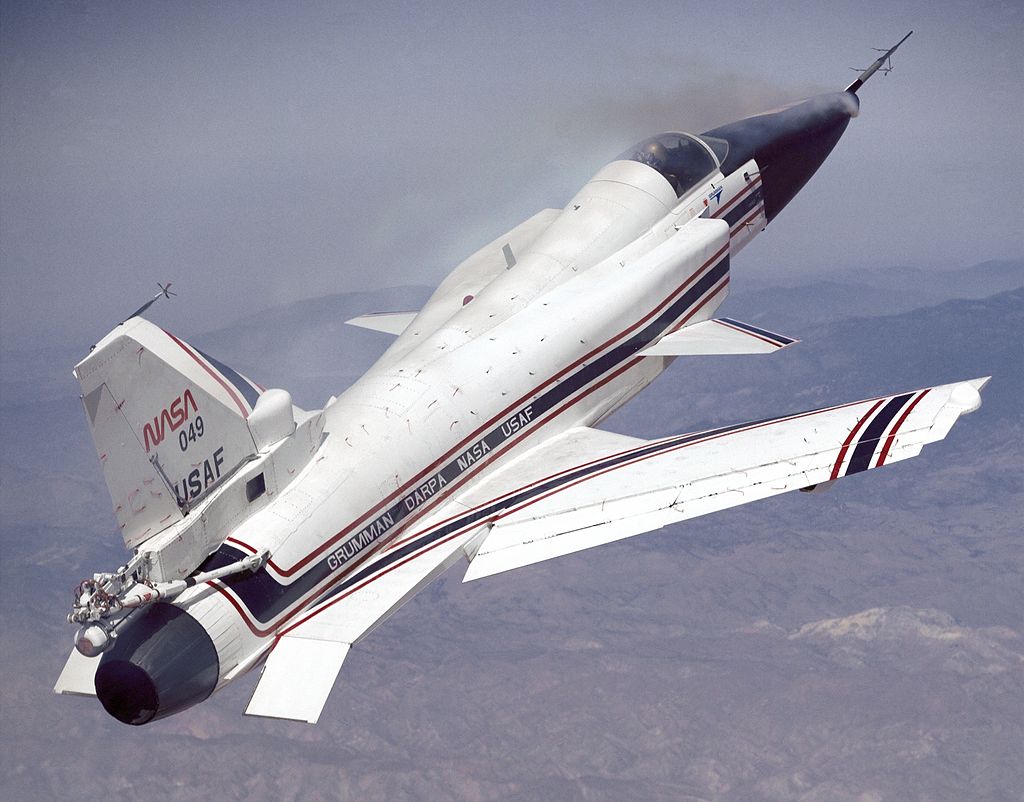
Grumman X-29 with forward-swept wings
In this manner, straight fibre composites allow structural engineers to change the stiffness and strength properties through the thickness in order to tailor the structural behaviour. The concept of variable stiffness composites adds a further dimension to the capability for tailoring. Currently this is achieved by spatially varying the point wise fiber orientations by actively steering individual fibre tows using automatic fibre placement machines. One early application that was considered by researchers was improving the stress concentrations around holes by steering fibres around them.
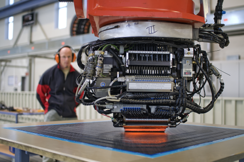
Automated Fibre Placement machine (2)
This concept can be generalised by aligning fibres with the direction of local primary load paths which could vary across different parts of the structure. Tow steering creates the possibility for designing blended structures by facilitating smooth transitions between areas with different layup requirements. One promising application of variable stiffness composites is in buckling and postbuckling optimisation of flat and curved panels. As a panel is compressed uni-axially the capability of the panel to resist transverse bending loads reduces until a critical level is reached where the panel has lost all capability to sustain any bending loads. At this point known as the buckling load, the fundamental state of compression becomes unstable and the panel buckles outward in a single or multiple waves. It has been found that variable stiffness composites can double the buckling load of flat panels by favourably redistributing the load paths in the fundamental, pre-buckling compression state. Essentially, the middle of the panel where the buckling waves will occur is offloaded, and the edges of the panel are forced to take more load. Thus, the aim is to redirect loads to locally supported regions and remove load from regions remote from supported boundaries. This concept has also been extended to improving aircraft fuselage sections and blade-stiffened panels.
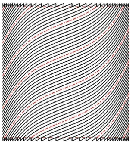
A variable angle tow laminate (3)
This new technology is viewed as a promising candidate for further reducing the mass of future aerospace structures. In fact recently NASA Langley Research Centre announced that they are investing heavily in this capability. The possibility of manufacturing integrated structures with smooth flow of material between components and minimal joints will not only revolutionise stress-based design, but also simplify manufacturing and facilitate entirely new aircraft designs that are currently unfeasible. In trees for example, there is a smooth transition of fibres from the trunk into the branches to strengthen the connecting joint. With the variable stiffness capabilities investigated by NASA we could apply this concept to simplify and even strengthen critical interfaces such as fuselage-wing connections.
References
(1) http://www.astm.org/HTTP/IMAGES/70104.gif
(2) http://csmres.co.uk/cs.public.upd/article-images/Premium-nordenham.jpg
(3) Kim et al. (2012). “Continuous Tow Shearing for Manufacturing Variable Angle Tow Composites”. Composites: Part A, 43, pp. 1347-1356
