(Caveat: There is a little bit more maths in this post than usual. I have tried to explain the equations as good as possible using diagrams. In any case, the real treat is at the end of the post where I go through the design of rocket nozzles. However, understanding this design methodology is naturally easier by first reading what comes before.)
One of the most basic equations in fluid dynamics is Bernoulli’s equation: the relationship between pressure and velocity in a moving fluid. It is so fundamental to aerodynamics that it is often cited (incorrectly!) when explaining how aircraft wings create lift. The fact is that Bernoulli’s equation is not a fundamental equation of aerodynamics at all, but a particular case of the conservation of energy applied to a fluid of constant density.
The underlying assumption of constant density is only valid for low-speed flows, but does not hold in the case of high-speed flows where the kinetic energy causes changes in the gas’ density. As the speed of a fluid approaches the speed of sound, the properties of the fluid undergo changes that cannot be modelled accurately using Bernoulli’s equation. This type of flow is known as compressible. As a rule of thumb, the demarcation line for compressibility is around 30% the speed of sound, or around 100 m/s for dry air close to Earth’s surface. This means that air flowing over a normal passenger car can be treated as incompressible, whereas the flow over a modern jumbo jet is not.
The fluid dynamics and thermodynamics of compressible flow are described by five fundamental equations, of which Bernoulli’s equation is a special case under the conditions of constant density. For example, let’s consider an arbitrary control volume of fluid and assume that any flow of this fluid is
- adiabatic, meaning there is no heat transfer out of or into the control volume.
- inviscid, meaning no friction is present.
- at constant energy, meaning no external work (for example by a compressor) is done on the fluid.
This type of flow is known as isentropic (constant entropy), and includes fluid flow over aircraft wings, but not fluid flowing through rotating turbines.
At this point you might be wondering how we can possible increase the speed of a gas without passing it through some machine that adds energy to the flow?
The answer is the fundamental law of conservation of energy. The temperature, pressure and density of a fluid at rest are known as the stagnation temperature, stagnation pressure and stagnation density, respectively. These stagnation values are the highest values that the gas can possibly attain. As the flow velocity of a gas increases, the pressure, temperature and density must fall in order to conserve energy, i.e. some of the internal energy of the gas is converted into kinetic energy. Hence, expansion of a gas leads to an increase in its velocity.
The isentropic flow described above is governed by five fundamental conservation equations that are expressed in terms density (


– Conservation of mass:
– Conservation of linear momentum:
– Conservation of energy:
– Equation of state:
– Conservation of entropy (in adiabatic and inviscid flow only):


where 

The Speed of Sound
Fundamental to the analysis of supersonic flow is the concept of the speed of sound. Without knowledge of the local speed of sound we cannot gauge where we are on the compressibility spectrum.
As a simple mind experiment, consider the plunger in a plastic syringe. The speed of sound describes the speed at which a pressure wave is transmitted through the air chamber by a small movement of the piston. As a very weak wave is being transmitted, the assumptions made above regarding no heat transfer and inviscid flow are valid here, and any variations in the temperature and pressure are small. Under these conditions it can be shown from only the five conservation equations above that the local speed of sound within the fluid is given by:

The term 


Why is the speed of sound purely a function of temperature?
Well, the temperature of a gas is a measure of the gas’ kinetic energy, which essentially describes how much the individual gas molecules are jiggling about. As the air molecules are moving randomly with differing instantaneous speeds and energies at different points in time, the temperature describes the average kinetic energy of the collection of molecules over a period of time. The higher the temperature the more ferocious the molecules are jiggling about and the more often they bump into each other. A pressure wave momentarily disturbs some particles and this extra energy is transferred through the gas by the collisions of molecules with their neighbours. The higher the temperature, the quicker the pressure wave is propagated through the gas due to the higher rate of collisions.
This visualisation is also helpful in explaining why the speed of sound is a special property in fluid dynamics. One possible source of an externally induced pressure wave is the disturbance of an object moving through the fluid. As the object slices through the air it collides with stationary air particles upstream of the direction of motion. This collision induces a pressure wave which is transmitted via the molecular collisions described above. Now imagine what happens when the object is travelling faster than the speed of sound. This means the moving object is creating new disturbances upstream of its direction of motion at a faster rate than the air can propagate the pressure waves through the gas by means of molecular collisions. The rate of pressure wave creation is faster than the rate of pressure wave transmission. Or put more simply, information is created more quickly than it can be transmitted; we have run out of bandwidth. For this reason, the speed of sound marks an important demarcation line in fluid dynamics which, if exceeded, introduces a number of counter-intuitive effects.
Given the importance of the speed of sound, the relative speed of a body with respect to the local speed of sound is described by the Mach Number:

The Mach number is named after Ernst Mach who conducted many of the first experiments on supersonic flow and captured the first ever photograph of a shock wave (shown below).

As described previously, when an object moves through a gas, the molecules just ahead of the object are pushed out of the way, creating a pressure pulse that propagates in all directions (imagine a spherical pressure wave) at the speed of sound relative to the fluid. Now let’s imagine a loudspeaker emitting three sound pulses at equal intervals, 


If the object is stationary, then the three sound pulses at times 


However, if the object starts moving in one direction, the centre of the spheres shift to the side and the sound pulses bunch up in the direction of motion and spread out in the opposite direction. A bystander listening to the sound pulses upstream of the loudspeaker would therefore hear a higher pitched sound than a downstream bystander as the frequency the sound waves reaching him are higher. This is known as the Doppler effect.
If the object now accelerates to the local speed of sound, then the centres of the sound pulse spheres will be travelling just as fast as the sound waves themselves and the spherical waves all touch at one point. This means no sound can travel ahead of the loudspeaker and consequently an observer ahead of the loudspeaker will hear nothing.
Finally, if the loudspeaker travels at a uniform speed greater than the speed of sound, then the loudspeaker will in fact overtake the sound pulses it is creating. In this case, the loudspeaker and the leading edges of the sound waves form a locus known as the Mach cone. An observer standing outside this cone is in a zone of silence and is not aware of the sound waves created by the loudspeaker.
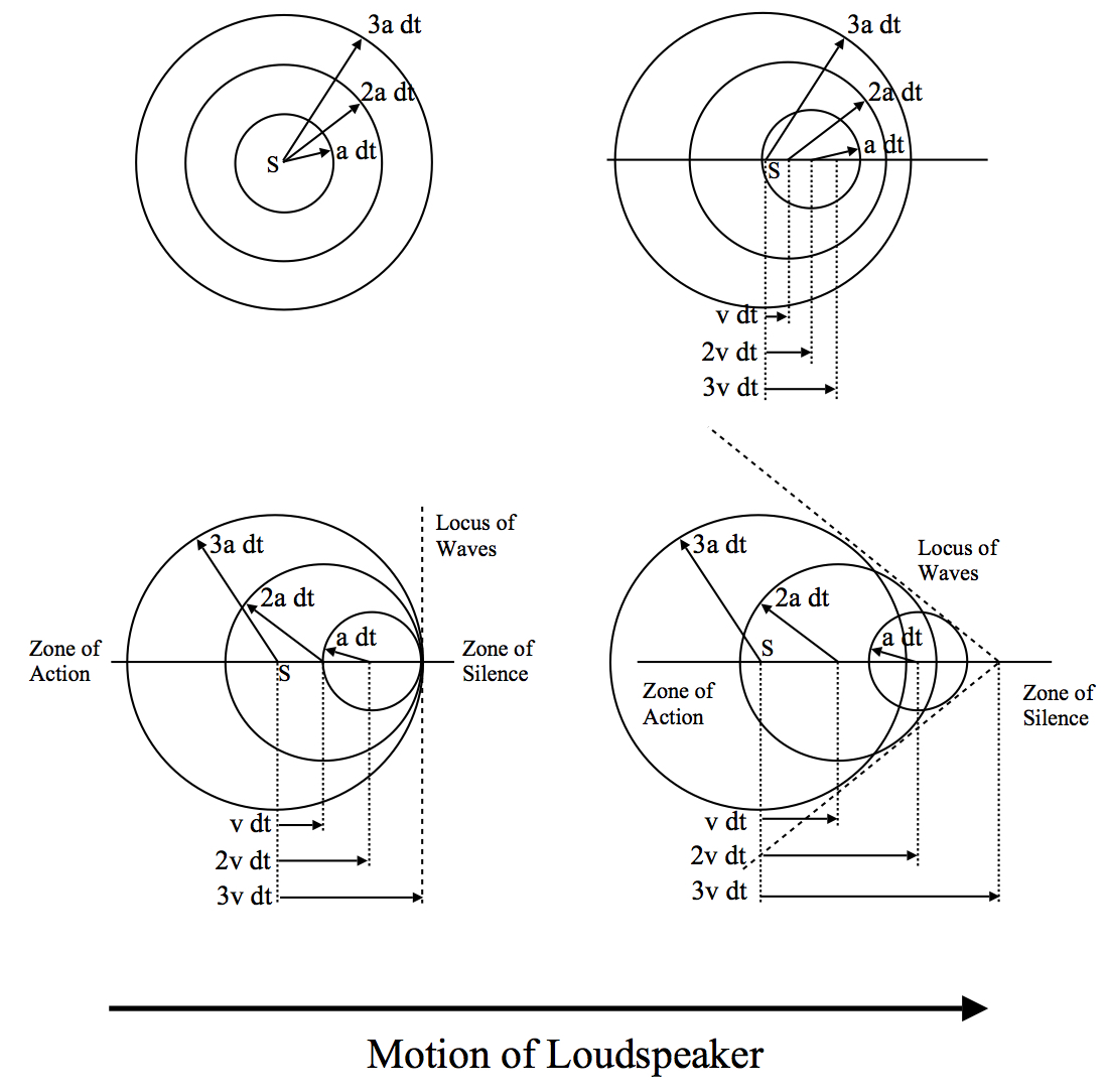
S is the starting point of the load speaker which then moves to the right of the screen emitting three sound pulses at times dt, 2dt and 3dt.
The half angle of this cone is known as the Mach angle and is equal to

and therefore 

As mentioned previously, the temperature, pressure and density of the gas all fall as the flow speed of the gas increases. The relation between Mach number and temperature can be derived directly from the conservation of energy (stated above) and is given by:
where 

An intuitive way of explaining the relationship between temperature and flow speed is to return to the description of the vibrating gas molecules. Previously we established that the temperature of a gas is a measure of the kinetic energy of the vibrating molecules. Hence, the stagnation temperature is the kinetic energy of the random motion of the air molecules in a stationary gas. However, if the gas is moving in a certain direction at speed then there will be a real net movement of the air molecules. The molecules will still be vibrating about, but at a net movement in a specific direction. If the total energy of the gas is to remain constant (no external work), some of the kinetic energy of the random vibrations must be converted into kinetic energy of directed motion, and hence the energy associated with random vibration, i.e. the temperature, must fall. Therefore, the gas temperature falls as some of the thermal internal energy is converted into kinetic energy.
In a similar fashion, for flow at constant entropy, both the pressure and density of the fluid can be quantified by the Mach number.


In this regard the Mach number can simply be interpreted as the degree of compressibility of a gas. For small Mach numbers (M< 0.3), the density changes by less than 5% and this is why the assumptions of constant density underlying Bernoulli’s equation are applicable.
An Application: Convergent-divergent Nozzles
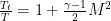
In typical engineering applications, compressible flow typically occurs in ducts, e.g. engine intakes, or through the exhaust nozzles of afterburners and rockets. This latter type of flow typically features changes in area. If we consider a differential, i.e. infinitesimally small control volume, where the cross-sectional area changes by 


Without solving this equation for a specific problem we can reveal some interesting properties of compressible flow:
- For M < 1, i.e. subsonic flow,
with
a positive constant. This means that increasing the flow velocity is only possible with a decrease in cross-sectional area and vice versa.
- For M = 1, i.e. sonic flow
. As
and therefore the area must be a minimum for sonic flow.
- For M > 1, i.e. supersonic flow
. This means that increasing the flow velocity is only possible with an increase in cross-sectional area and vice versa.
Subsonic and supersonic flow in nozzles
Hence, because of the term 

The flow through such a bell-shaped convergent-divergent nozzle is driven by the pressure difference between the combustion chamber and the nozzle outlet. In the combustion chamber the gas is basically at rest and therefore at stagnation pressure. As it exits the nozzle, the gas is typically moving and therefore at a lower pressure. In order to create supersonic flow, the first important condition is a high enough pressure ratio between the combustion chamber and the throat of the nozzle to guarantee that the flow is sonic at the throat. Without this critical condition at the throat, there can be no supersonic flow in the divergent section of the nozzle.
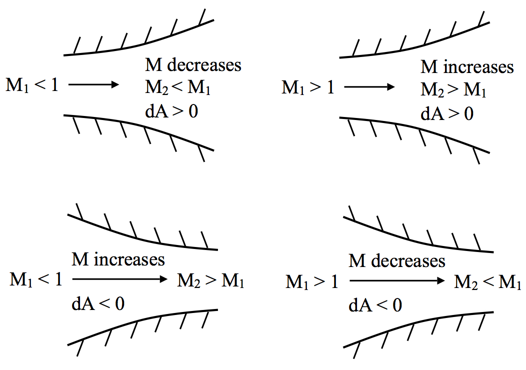
We can determine this exact pressure ratio for dry air (

Therefore, a pressure ratio greater than or equal to 1.893 is required to guarantee sonic flow at the throat. The temperature at this condition would then be:
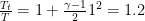
or 1.2 times smaller than the temperature in the combustion chamber (as long as there is no heat loss or work done in the meantime, i.e. isentropic flow).
Shock Waves
The term “shock wave” implies a certain sense of drama; the state of shock after a traumatic event, the shock waves of a revolution, the shock waves of an earthquake, thunder, the cracking of a whip, and so on. In aerodynamics, a shock wave describes a thin front of energy, approximately 
The Prandtl relation provides a means of calculating the speed of the fluid flow after a normal shock, given the flow speed before the shock.

where 

We can further extend the Prandtl relation to express all flow properties (speed, temperature, pressure and density) in terms of the upstream Mach number 

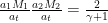
and because we know the relationship between temperature, stagnation temperature and Mach number from above:
substitution for states 1 and 2 the Prandtl relation is transformed into:

This equation looks a bit clumsy but it is actually quite straightforward given that the terms involving
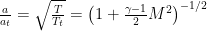
Change in Mach number across a shock wave
It is clear from the figure that for 


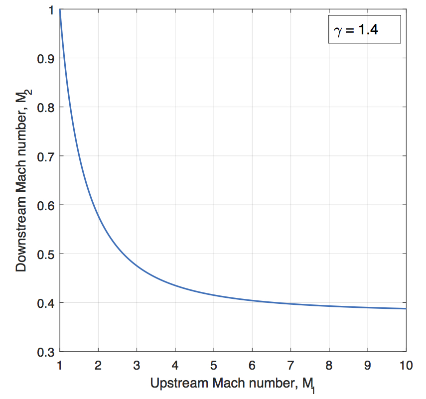
Both the temperature and pressure ratios increase with higher Mach number such that both 


Pressure and density ratios across a shock wave
Even though the Rankine equations are valid mathematically for subsonic flow, the predicted fluid properties lead to a decrease in entropy, which contradicts the Second Law of Thermodynamics. Hence, shock waves can only be created in supersonic flow and the pressure, temperature and density always increase across it.
Designing Convergent-divergent Nozzles
With our new-found knowledge on supersonic flow and nozzles we can now begin to intuitively design a convergent-divergent nozzle to be used on a rocket. Consider two reservoirs connected by a convergent-divergent nozzle (see figure below).
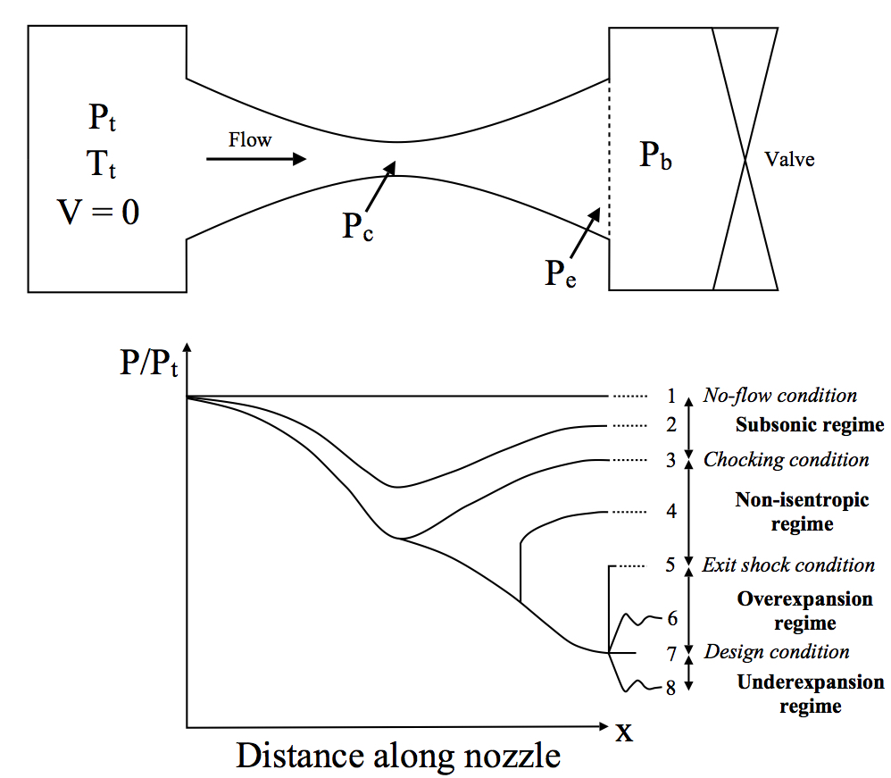
Convergent-divergent nozzle schematic and variations of pressure along the length of the nozzle
The gas within the upstream reservoir is stagnant at a specific stagnation temperature 


- The no-flow condition: In this case the valve is closed and
. This is the trivial condition where nothing interesting happens. No flow, nothing, boring.
- Subsonic flow regime: The valve is opened slightly and the flow is entirely subsonic throughout the entire nozzle. The pressure decreases from the stagnant condition in the upstream reservoir to a minimum at the throat, but because the flow does not reach the critical pressure ratio
, the flow does not reach Mach 1 at the throat. Hence, the flow cannot accelerate further in the divergent section and slows down again, thereby increasing the pressure. The exit pressure
- Choking condition: The back pressure has now reached a critical condition and is low enough for the flow to reach Mach 1 at the throat. Hence,
) and therefore the divergent section of the nozzle still acts as a diffuser; the flow does not go supersonic. However, as the flow can not go faster than Mach 1 at the throat, the maximum mass flow rate has been achieved and the nozzle is now choked.
- Non-isentropic flow regime: Lowering the back pressure further means that the flow now reaches Mach 1 at the throat and can then accelerate to supersonic speeds within the divergent portion of the nozzle. The flow in the convergent section of the nozzle remains the same as in condition 3) as the nozzle is choked. Due to the supersonic flow, a shock wave forms within the divergent section turning the flow from supersonic into subsonic. Downstream of the shock the divergent nozzle now diffuses the flow further to equalise the back pressure and exit pressure (
- Exit plane shock condition: This is the limiting condition where the shock wave in the divergent portion has moved exactly to the exit plane. At the exit of the nozzle there is an abrupt increase in pressure at the exit plane and therefore the exit plane pressure and back pressure are still the same (
- Overexpansion flow regime: The back pressure is now low enough that the flow is subsonic throughout the convergent portion of the nozzle, sonic at the throat and supersonic throughout the entire divergent portion. This means that the exit pressure is now lower than the gas pressure (the flow is overexpanded), causing it to suddenly contract once it exits the nozzle. These sudden compressions cause nonisentropic oblique pressure waves which cannot be modelled using the simple 1D flow assumptions we have made here.
- Nozzle design condition: At the nozzle design condition the back pressure is low enough to match the pressure of the supersonic flow at the exit plane. Hence, the flow is entirely isentropic within the nozzle and inside the downstream reservoir. As described in a previous post on rocketry, this is the ideal operating condition for a nozzle in terms of efficiency.
- Underexpansion flow regime: Contrary to the over expansion regime, the back pressure is now lower than the exit pressure of the supersonic flow, such that the exit flow must expand to equilibrate with the reservoir pressure. In this case, the flow is again governed by oblique pressure waves, which this time expand outward rather than contract inward.
Thus, as we have seen the flow inside and outside of the nozzle is driven by the back pressure and by the requirement of the exit pressure and back pressure to equilibrate once the flow exits the nozzle. In some cases this occurs as a result of shocks inside the nozzle and in others as a result of pressure waves outside. In terms of the structural mechanics of the nozzle, we obviously do not want shock to occur inside the nozzle in case this damages the structural integrity. Ideally, we would want to operate a rocket nozzle at the design condition, but as the atmospheric pressure changes throughout a flight into space, a rocket nozzle is typically overexpanded at take-off and underexpanded in space. To account for this, variable area nozzles and other clever ideas have been proposed to operate as close as possible to the design condition.

Hi< Just a very quick question looking for a very simple answer.
Is a rocket engine more efficient in an atmosphere or in Space?
In terms of converting the combustion into rocket velocity specifically.
The ejected gas direction can be more constrained to the ideal direction in an atmosphere than a nozzle can achieve in a vacuum. that is my understanding, is it right?
Rocket nozzles are more efficient in a vacuum. When you fire an engine in an atmosphere, you must keep the pressure of the exhaust gas greater than (or at least close to) atmospheric pressure, or the atmosphere will flow back into the engine and mess up the thrust. This means the engine cannot expand as far as it could in a vacuum, where this constraint is functionally nonexistent.