 Norris Tie is the CEO of Exosonic, a California-based startup that is developing a low sonic boom supersonic passenger aircraft. Norris holds an engineering degree from UCLA, an MBA from Stanford, and before starting Exosonic worked on supersonic aircraft at Northrup Grumman, Virgin Galactic and Lockheed Martin Skunk Works.
What differentiates Exosonic from other upstarts in the reviving supersonic aircraft space is that the company is specifically focusing on reducing the intensity of sonic booms. Current regulation forbids supersonic flights across America to minimise noise pollution; a restriction which significantly limited the routes that the first supersonic airliner, the Concorde, could fly. To soften sonic booms, Exosonic is using a concept and technology originally pioneered by NASA known as shaped sonic booms. As a first step, Exosonic has partnered with the US Air Force to develop a supersonic executive transport aircraft that will provide US leaders and diplomats rapid transportation around the world. In this episode of the Aerospace Engineering Podcast, Norris and I talk about
- his life-long inspiration for speeding-up air travel
- the theory behind shaped sonic booms
- what is different about designing supersonic aircraft
- and the economics of supersonic flight
Podcast: Play in new window | Download | Embed
Subscribe: Apple Podcasts | TuneIn | RSS
This episode of the Aerospace Engineering Podcast is brought to you by my patrons on Patreon. Patreon is a way for me to receive regular donations from listeners whenever I release a new episode, and with the help of these generous donors I have been able to pay for much of the expenses, hosting and travels costs that accrue in the production of this podcast. If you would like to support the podcast as a patron, then head over to my Patreon page. There are multiple levels of support, but anything from $1 an episode is highly appreciated. Thank you for your support!
Selected Links from the Episode
- Exosonic webpage, Twitter & LinkedIn
- Exosonic’s supersonic Air Force One concept:
- Exosonic is hiring
- Shaped Sonic Booms
- NASA Book: Quieting the Boom
 Alexander Wicks is the Chief Development Officer at the California-based startup Momentus Space. Momentus is developing the in-space equivalent of the connecting flight we all know from airline operations.
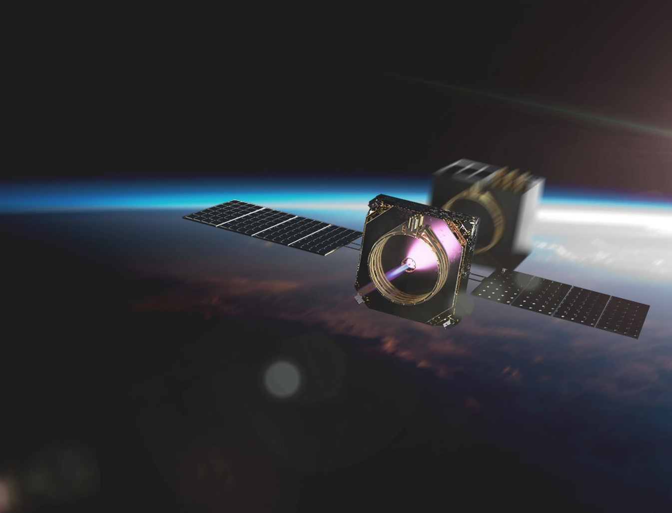
To affordably launch small satellites into orbit, operators and manufacturers of small satellites are generally forced to share a ride on one big rocket. This approach is economical, but has one major downside: not every satellite on the ride share can be launched into its ideal orbit. Momentus is developing the transfer vehicle that then allows a satellite to reach its customisable orbit 10 times cheaper than booking a dedicated launch on the first vehicle. This capability essentially allows the next generation of satellites to reach previously unreachable locations more efficiently and more inexpensively than before.
The transfer vehicle that Momentus is developing is powered by water plasma propulsion, and the same propulsion technology also opens the door to the next phase of space exploration. For example, missions into deep space, water prospecting and delivery throughout the solar system, in-space manufacturing, and space tourism. In this episode of the podcast you will learn about:
- how Momentus got started
- the need and benefits of Momentus’ transfer vehicle
- the principles of water plasma propulsion
- and the types of missions the technology enables
Podcast: Play in new window | Download | Embed
Subscribe: Apple Podcasts | TuneIn | RSS
This episode of the Aerospace Engineering Podcast is brought to you by my patrons on Patreon. Patreon is a way for me to receive regular donations from listeners whenever I release a new episode, and with the help of these generous donors I have been able to pay for much of the expenses, hosting and travels costs that accrue in the production of this podcast. If you would like to support the podcast as a patron, then head over to my Patreon page. There are multiple levels of support, but anything from $1 an episode is highly appreciated. Thank you for your support!
Selected Links from the Episode
 Euan Wielewski is the co-founder and CEO at Anomalous Technologies, a start-up based in Edinburgh, Scotland using the latest machine learning and artificial intelligence (AI) technologies to enable better quality control of manufactured components.
As aerospace engineers we know that quality control and inspection of flight-critical hardware is essential to guarantee safe operation of aircraft. Human visual inspection is a subjective and analogue process, which means that flight hardware is typically double and triple-checked to high levels of accuracy. This is where the AI tools developed by Anomalous Technologies are invaluable. By making inspection digital, operational traceability is immediately enhanced. Furthermore, digitisation allows the human inspection process to be accompanied by statistical tools that reduce the error rate of missed defects and improve inspection efficiency.
Anomalous are already working with global aerospace companies such as Rolls Royce and Boeing, and the company is currently a member of the first cohort of the ATI Boeing Accelerator. In this episode of the podcast, Euan and I talk about:
- his broad background in aerospace engineering
- the challenges of human inspection in the aerospace industry
- how data-centric methods such as AI tools can help improve inspection accuracy and efficiency
- and how Anomalous is using their analytic tools to help out in the current Coronavirus pandemic.
Podcast: Play in new window | Download | Embed
Subscribe: Apple Podcasts | TuneIn | RSS
This episode of the Aerospace Engineering Podcast is brought to you by my patrons on Patreon. Patreon is a way for me to receive regular donations from listeners whenever I release a new episode, and with the help of these generous donors I have been able to pay for much of the expenses, hosting and travels costs that accrue in the production of this podcast. If you would like to support the podcast as a patron, then head over to my Patreon page. There are multiple levels of support, but anything from $1 an episode is highly appreciated. Thank you for your support!
Selected Links from the Episode
 Sergey Kiselev is the Head of Europe of the sustainable aviation company ZeroAvia. ZeroAvia is working on the first practical zero-emission aviation powertrain fuelled by hydrogen. Even though CO2 emissions of the aviation industry currently only account for 2-3% of the global output, passenger numbers are expected to grow continuously for the next 30 years, such that solutions transitioning to emission-free powertrains need to be formulated, tested and certified now.
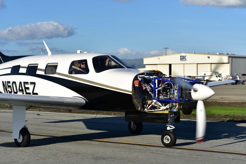
ZeroAvia has developed a new powertrain that couples hydrogen gas with a fuel cell to drive an electric motor that spins a propeller. This zero emission powertrain currently promises to deliver a 300 mile zero-emission range in a ten-seater fixed-wing aircraft. One of the great things about ZeroAvia is that the company is taking advantage of the economics of renewable energy sources. Due to the intermittency of solar and wind energy, there are times when the electric output from renewable sources far outstrips demand and is therefore cheaply available. It is in these times of high supply that ZeroAvia can split water into its constituents, oxygen and hydrogen. In this episode of the aerospace engineering podcast, Sergey and I talk about:
- how ZeroAvia got started and what the company is trying to achieve
- ZeroAvia’s vision of emission-free regional travel
- the ZeroAvia powertrain
- and much, much more.
Podcast: Play in new window | Download | Embed
Subscribe: Apple Podcasts | TuneIn | RSS
This episode of the Aerospace Engineering Podcast is brought to you by my patrons on Patreon. Patreon is a way for me to receive regular donations from listeners whenever I release a new episode, and with the help of these generous donors I have been able to pay for much of the expenses, hosting and travels costs that accrue in the production of this podcast. If you would like to support the podcast as a patron, then head over to my Patreon page. There are multiple levels of support, but anything from $1 an episode is highly appreciated. Thank you for your support!
Selected Links from the Episode
 Alexandra Gravereaux is a Ground Systems Engineer for the space startup Astroscale. Astroscale is a global company headquartered in Tokyo, Japan with offices in the UK, Singapore and the USA, and is developing technological and regulatory solutions for space debris removal. The mission of Astroscale is to guarantee the long-term safety of spaceflight and orbital sustainability by developing end-of-life services for satellites and active debris removal. This relates to removing space junk that has accumulated due to defunct satellites and jettisoned rocket interstages; guaranteeing that regulations are in place to prevent the build-up of further space junk; and technological solutions to de-orbit defunct satellites.
The company is currently designing and manufacturing its End-of-Life Service by Astroscale programme (ELSA), a spacecraft retrieval service for satellite operators. The first demonstration mission, known as ELSA-d, is scheduled to launch in 2020, and will demonstrate Astroscale’s technology for debris docking and removal in orbit. In this episode, Alex and I talk about:
- her background in the space sector
- the problem of accumulating space debris and how to deal with it
- the details of Astroscale’s ELSA-d demonstration mission in 2020
- and Alex’s expertise as a ground systems engineer.
Podcast: Play in new window | Download | Embed
Subscribe: Apple Podcasts | TuneIn | RSS
This episode of the Aerospace Engineering Podcast is brought to you by my patrons on Patreon. Patreon is a way for me to receive regular donations from listeners whenever I release a new episode, and with the help of these generous donors I have been able to pay for much of the expenses, hosting and travels costs that accrue in the production of this podcast. If you would like to support the podcast as a patron, then head over to my Patreon page. There are multiple levels of support, but anything from $1 an episode is highly appreciated. Thank you for your support!
Selected Links from the Episode
This is the second guest post by Jason D’souza, a recent MSc Graduate in Aerospace Vehicle Design from the University of Cranfield in the UK. Winglets are aerodynamic devices that feature on many modern commercial aircraft, but do have certain drawbacks. In this post, Jason considers a slightly different, on-demand system, known as a fluidic winglet and demonstrates its interesting properties using CFD analyses.
Turmoil in The Sky
The environmental impact of aircraft carbon footprint is of rising importance to all operators as consumer demand for air travel continues to grow. The aviation industry holds a small contribution to global emissions, but unequivocally, it is one of the fastest growing contributors to emissions. Since the 1970s, when the price of aviation fuel began to spiral upward, airlines and aircraft manufacturers have explored many ways to reduce fuel consumption by improving the operating efficiency of their aircraft. Fuel economy concerns have been particularly important for operators of commercial aircraft, which typically fly many hours per day in competitive markets. Hence, there are also good economic incentives for reducing emissions, since reduced emissions are naturally related to reduced fuel consumption and savings in fuel expenditure for air carriers. A great potential source for fuel savings is reducing parasitic drag of the airframe, such as inherent wingtip vortices.
Introduction to Wingtip Vortices
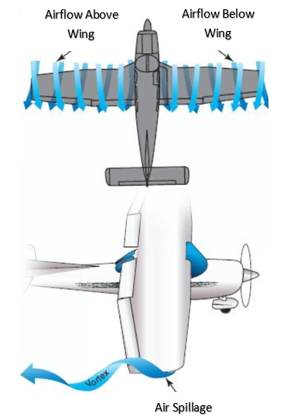
Wingtip vortices are schematically illustrated in Figure 1. If a wing is producing lift, a pressure differential exists between the upper and lower surfaces, i.e. for positive lift, the static pressure on the upper surface will be less than on the lower surface. At the tips and trailing edges of the wing, the existence of this pressure differential creates a vortex where the high-pressure air below the wing spills onto the low-pressure area above the wing to form a swirling tunnel of turbulent air along (top of Figure 1) and behind the wing (bottom of Figure 1). The vortex is strongest when the angle of attack is high, such as during take-off and landing, because the pressure differential at high angles of attack is greatest during these phases.
Why are wingtip vortices detrimental to aircraft aerodynamics?
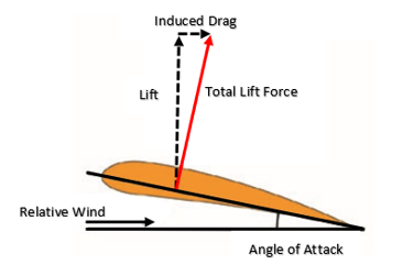
To create a specific lift coefficient with the airfoil section, a certain angle of attack must exist between the airfoil chord line and the relative wind; see Figure 2. However, as the total lift force is developed perpendicular to the wing chord line, it is angled slightly backwards. There are two problems occurring here; firstly, some of the total lift force is now deflected backwards leading to the creation of lift-induced drag, illustrated in Figure 2; and secondly, there is a smaller component of lift pointing upwards to counterbalance the weight of the aircraft. Both of these effects are to the detriment of the lift-to-drag ratio, a key efficiency parameter in aircraft design. Thus, as a result of this decrease in vertical lift, the wing must be given an angle of attack greater than the current section angle in order to generate more lift to account for the inclination of the total lift force. However, any increase in the angle of attack also increases the lift-induced drag. Wingtip vortices exacerbate this lift-induced drag by causing the total lift force to point even further backward. A number of possible solutions exist for mitigating the effect of vortex-induced drag, but conventionally, wingtip retrofits, commonly known as winglets, are used to mitigate the problem.
How do winglets help to improve the situation and what are some of the drawbacks?
One of the visible actions taken by commercial airframe manufacturers to reduce wingtip vortices is the modification of an aircraft’s wingtip by installing, as shown in Figure 3, near-vertical “winglets”. Experience shows that these tip devices reduce block fuel consumption (total fuel burn from engine start at the beginning of a flight to engine shutdown at the end of the flight) of the modified aircraft by 3% – 5%, depending on trip length [1].
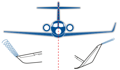
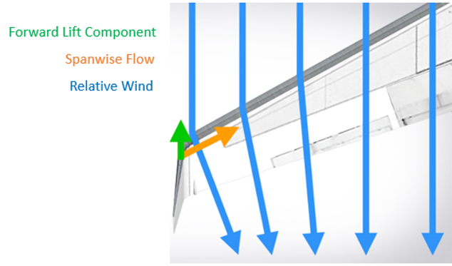
Winglets are airfoil-shaped structures that also produce lift but are orientated inwards towards the fuselage relative to the rest of the wing. The presence of winglets changes the effect that wingtip vortices have on lift and drag. The winglets cause the relative wind to bend inwards towards the fuselage, creating a forward vector of lift in the direction of flight counteracting some of the induced drag, as illustrated in Figure 4.
However, winglets do not operate effectively under all conditions throughout the flight envelope and incur an added mass penalty. So, the question is whether winglets conserve more fuel by reducing drag than the extra fuel required to carry their mass? An inherent problem with winglets is their susceptibility to flutter and increased bending stresses in the winglet fold area. In fact, under some flight conditions an equal area, flat span extension can be a more effective and less risky design solution. Lastly, winglets are always present in flight, as they are fixed devices attached to the tips of wings, and because they are fixed surfaces, they provide their best lift-induced drag reduction for a single design point. Hence, a more on-demand and active, rather than passive, type of control device could be of benefit. One example is the use of a “Fluidic Winglet”.
What is a fluidic winglet and how does it work?
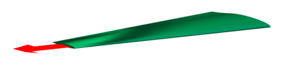
A fluidic winglet is a system architecture that can provide a controlled stream of air ejected outwards in the vicinity of the wingtip, as shown in Figure 5, to create an aerodynamic force strong enough to disrupt the vortex formation. This system architecture could potentially produce the same benefits as a winglet without a visible increase in wingspan.
The pressurised air for the fluidic winglet could be taken from:
- The jet engine
- The aircraft surface
- The leading edge of the wing
- An internal pressurised air tank
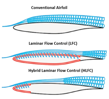
RAM drag (a common source of system-induced drag caused by taking in air, typically for cooling purposes) and weight penalties introduced from the above systems must be considered when evaluating the system. If air is taken from the aircraft surface, then a Laminar Flow Control (LFC), a Hybrid Laminar Flow Control (HLFC) system, or a duct located at the wing leading edge stagnation pressure line could be appropriate. However, this would not result in high jet momenta and will be limited to lower mass flow rates [5]. The LFC and HLFC systems are active boundary layer control techniques, shown in Figure 6, that help to maintain the laminar flow state by means of suction onto the wing surface during flow states that would otherwise be transitional or turbulent.
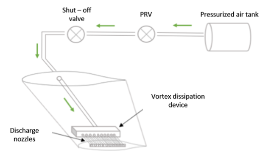
If the air used to operate the fluidic winglet is taken from a separate pressurised tank inside the fuselage, the fluidic system could look something like depicted in Figure 7. Once the pilot signal is received, a solenoid valve allows the air to be released from the tank where it is regulated to provide the required exit velocity. The air then flows into the vortex dissipation device where the air is distributed to the discharge nozzles. If the exit pressure past the pressure regulating valve (PRV) exceeds the design limit, a shut-off valve ahead of the PRV will not allow fluid to pass above a certain set pressure as a fail-safe.
Analysis – What potential benefits of the fluidic winglet can be expected over conventional alternatives?
In order to ascertain the potential benefits of the fluidic winglet, the lift coefficient (CL), drag coefficient (CD) and lift-to-drag ratio (CL/CD) of three models are investigated using ANSYS Fluent, and the results are extracted and summarised in Figure 8. The models designed are:
- A clean wing (CW) with no winglet attached: designed from a NASA HSNLF (1)-0213 airfoil with a leading-edge sweep angle of 33° and a taper ratio of 0.4.
- A wing with a raked winglet (WRW): designed from a NACA 0012 airfoil with 10% of wing semi-span and a taper ratio of 0.2 and with a sweep angle greater than that of the wing of about 57°.
- A wing with the fluidic winglet (WFW): this will not require a wingtip extension, and hence, there is no physical increase in the wing’s span. The fluidic winglet instead consists of a rectangular high-aspect ratio slot.
Note: The models do not have an aerodynamic twist consideration.
The boundary conditions that constitute the flow variables are: a freestream velocity of 50 m/s and an injection velocity three times the freestream (150 m/s) with a jet sweep angle equivalent to that of the wing sweep (i.e. the jet is co-linear with the wing). These models will be tested at high angles of attack of 7.5°, 10° and 12.5° to simulate the effect of the fluidic winglet on the vortex when it is strongest.
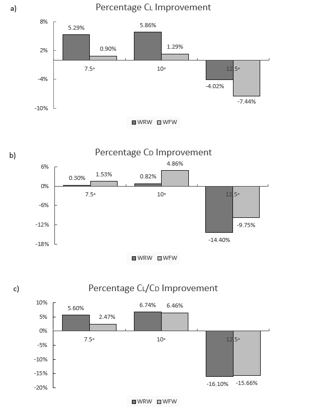
As illustrated in Figure 8c), the results indicate that having a tapered wingtip extension (i.e. a raked wingtip, WRW) provides improved aerodynamic efficiency (CL/CD) of 7% for an angle of attack of 10°, and generally better levels of drag reduction are expected at lower (7.5° and 10°) angles of attack than higher (12.5°) angles. As shown in Figure 8a), the WRW improves the lift coefficient much more than the fluidic wingtip (WFW). This is due to the increase in wing area added by the physical wingtip. However, this additional surface area causes a parasitic component of drag, which is why the WFW outperforms the WRW design in terms of drag coefficient, as shown in Figure 8b). Further, in Figure 8c) it appears that the WRW’s performance is reduced by 16% at an angle of attack of 12.5°, which occurs due to local wingtip stall. There are two reasons for this stall occurrence; firstly, the dissimilarity between the main wing airfoil and the raked winglet airfoil and secondly, the WRW is not twisted. The WRW should employ twist to avoid local stalling at such high angles of attack.
Similarly, the application of the fluidic WFW at high angles of attack leads to improvements to the wing’s aerodynamic efficiency. As shown in Figure 8c), at 7.5° angle of attack, the lift-to-drag ratio is increased by 2.5%, and at 10°, the lift-to-drag ratio is increased by 6.5%. However, for the 12.5° angle of attack, when the 50 m/s freestream air collides with the 150 m/s jet, stalling occurs locally, thus spoiling the lift and increasing drag. This stall condition occurs due to a local increase in the Reynolds number in the region where the freestream and jet efflux meet.
Nonetheless, because the fluidic winglet has no additional surface exposed, there is no increase in parasitic drag. This fact contributes to acceptable drag reductions as shown in Figure 8b). Hence, the overall enhancement of the lift-to-drag ratio between the WRW and the WFW is very similar emphasizing the capability of the WFW. The WRW is more effective at improving the lift, whereas the WFW is better at reducing drag. Furthermore, the WFW can be activated at any specific angle of attack, and has the potential to deliver better levels of drag reduction at more than a single design point during the flight envelope. Other benefits not only include potential improved fuel economy, but also improved payload-range capability, improved take-off performance, and less take-off noise.
How is the fluidic winglet able to improve the lift-to-drag ratio?
The WFW is able to improve aerodynamic efficiency by altering the chordwise lift distribution along the wingspan. It is generally well known that an elliptical lift distribution in the spanwise direction is optimal for reducing induced drag for a specific wing area and lift. First, as shown in Figure 9, the WFW (right figure) makes the lift distribution more elliptical than the clean wing (left figure). Furthermore, it is observed that, at high angles of attack, the sectional chordwise pressure distribution on the upper and lower surface of the WFW changes favourably from root to tip.
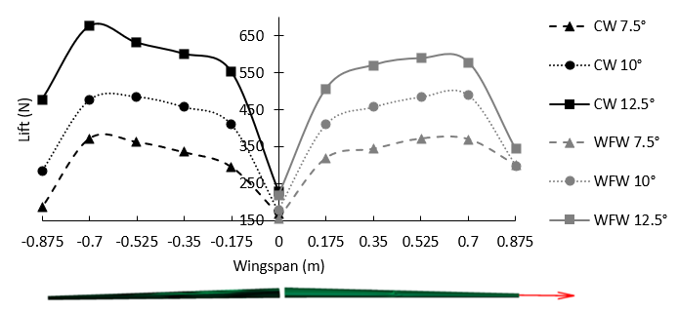
The spanwise variation in the sectional lift force, as shown in Figure 9, for the CW is observed to increase until the 80% wing semi-span location, at which point it drops off dramatically. This drop off in lift force towards the wingtip (100% wing semi-span position) is due to the creation of wingtip vortices that disrupt effective lift generation over the wing. It is clear that the aerodynamic lift force is considerably increased by the WFW towards the wingtip for the 7.5° and 10° conditions, thereby demonstrating the effectiveness of the jet efflux to increase the aerodynamic loading at the wingtips for the angles of attack tested herein. The only exception is the 12.5° angle of attack condition, where the addition of the fluidic jet efflux creates a local stall condition, as previously discussed above.
Additional thoughts – How could fluidic winglets be implemented?
It is important to evaluate aircraft inventory and identify the most suitable aircraft candidates for fluidic winglet modification. The process could be summarised under four main tasks:
- Examine the feasibility of modifying aircraft with fluidic winglets, to include a cost-effectiveness analysis of the modification in net present value (NPV) terms.
- Determine the market price of aviation fuel at which incorporating the fluidic winglets would be beneficial for each platform.
- Consider impact to aircraft maintenance and flight operations (including ground operations).
- Investment strategies to minimize the operator’s capital investment and maximize investment return.
These tasks call for a quantitative assessment of the costs and benefits of fluidic winglet modifications on a variety of platforms. In a comprehensive analysis, one would need to include the non-recurring engineering costs of wing analysis and fluidic system design, as well as the costs of materials, manpower, and out-of-service time to accomplish the modification, financial implications, training costs, potential impacts on maintenance docks, costs associated with software and technical manual revisions, and any impacts on maintenance, operations, or mission accomplishment.
In each case, the aircraft structure needs to be studied and determined to be appropriate; engineering design must be analysed in detail; modifications will need to be prototyped, tested, and certified; modification kits to be developed and flight manuals revised as required. Past commercial experience with aircraft that have installed conventional winglets has shown that there have been no significant impacts on aircraft maintenance, flight operations, or ground operations (gate space, taxiways, hangars, etc.) [1].
Conclusion
It is clear that aerodynamic improvements, including fluidic winglets, can make significant contributions to the efficiency of aircraft. In each case, however, the appropriateness of such structural/system modifications must be determined fleet by fleet. These decisions are very complex and will depend on many factors, including the design of the aircraft’s structures, systems design, design margin within those structures, the condition of the structures, mission profiles, utilisation rates, fuel consumption rates, fuel prices, and the remaining life of the aircraft. There are also other ways to reduce fuel consumption, many of which have already been adopted by commercial airlines. Nonetheless, the best solution is decided by economics rather than aerodynamics.
The design of the fluidic winglet combines several disciplines such as structures, manufacturing and assembly, systems, aerodynamic and flight dynamics. The selection of the most appropriate system air resource and subsequent system design will depend upon the jet efflux requirements of the fluidic winglet. The benefits of the concept are highly dependent upon the jet parameters like the jet momentum coefficient, jet dihedral, jet sweep, jet thickness and jet area as well as the boundary conditions. Higher jet momenta and smaller jet cross-sectional areas show promise to move the vortex centre further away from the wingtip to increase the effective wingspan. Jet sweep angles higher than the wing sweep angle are not suspected to provide improved results.
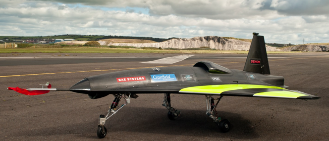
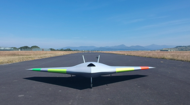
Since 2010, BAE Systems has set out to develop key technologies and skills with long-term collaboration from academia, industry and the UK government to create the combat air system of the future so that the UK can deliver more advanced capabilities through shared investment and revolutionise aircraft design. The first ever exhibit of fluidic flight control (i.e. no flaps, elevators or ailerons) begins with the FLAVIIR Demon Project (Flapless Air Vehicle Integrated Industrial Research program), a UAV showcasing new technology for the conventional flight control system. There are slots located on the wing’s trailing edge for the blown compressed air taken from the APU (Auxiliary Power Unit) to be curled either upwards (i.e. lowering the wing) or downwards (i.e. lifting the wing) to provide for control of the aircraft. This allows for a more seamlessly integrated design with fewer mechanically moving parts, and hence, a design with reduced edges and gaps that make the aircraft less observable on radar.
Similarly, in 2017 BAE Systems, in collaboration with the University of Manchester, revealed the first flight of MAGMA, a new UAV iteration showcasing novel control technologies for wing circulation control and fluidic thrust vectoring. The wing circulation control system takes air from the aircraft engine and blows it supersonically through the trailing edge of the wing to provide roll control for the aircraft. The fluidic thrust vectoring systems also uses blown air to deflect the main thrust allowing for the pitch direction of the aircraft to be changed. So far, flight tests have been promising and we are awaiting the first use of such circulation control in flight on gas turbine aircraft.
References
[1]National Research Council. ASSESSMENT OF WINGTIP MODIFICATIONS TO INCREASE THE FUEL EFFICIENCY OF AIRCRAFT, accessed 10/01/2020.
[2] Jeffrey (2008). Wingtip Vortices and Wake Turbulence Explained, accessed 10/01/2020.
[3] Mike C (2017). WHAT AM I: WINGLETS, accessed 10/01/2020.
[4] Colin C (2019). This Is How Winglets Work, accessed 10/01/2020.
[5] Ronald J (1998). Overview of Laminar Flow Control, NASA Technical Paper, accessed 10/01/2020.
[6] Krishnan K (2017). Review of hybrid laminar flow control systems, accessed 10/01/2020.
[7] Ben C (2010). DEMON UAV achieves historic first ‘flapless flight’, accessed 10/01/2020.
[8] Andrea K (2019). MAGMA: The future of flight, BAE Systems, accessed 10/01/2020.
 Wil Benton is the Venture & Ecosystem Director for the ATI Boeing Accelerator in London, UK. The Aerospace Technology Institute (ATI) is a UK organisation that creates the technology strategy for the UK aerospace sector and funds world-class research and development. The ATI recently launched a startup accelerator to accelerate the growth of new companies in industry 4.0 and sustainable development, with the aim of bolstering the growth and competitiveness of the UK aerospace industry. The programme is designed to help startups establish commercial relationships with global aerospace companies, like Boeing and GKN Aerospace, and to raise follow-on funding and engage with the wider UK aerospace sector. The first cohort of companies was recently announced and and you can check out a video of the selection day below.
Wil’s background is originally in the tech industry as a founder of Chew, a live streaming platform for DJ’s, as well as an angel investor and startup advisor for the startup accelerator Ignite. In this episode, Wil and I speak about:
- his career background and route into the aerospace industry
- the goal and operational principle of the ATI Boeing Accelerator
- some of the aerospace startups in the first cohort of the accelerator
- and Wil’s passion for entrepreneurship and STEM engagement
Podcast: Play in new window | Download | Embed
Subscribe: Apple Podcasts | TuneIn | RSS
This episode of the Aerospace Engineering Podcast is brought to you by my patrons on Patreon. Patreon is a way for me to receive regular donations from listeners whenever I release a new episode, and with the help of these generous donors I have been able to pay for much of the expenses, hosting and travels costs that accrue in the production of this podcast. If you would like to support the podcast as a patron, then head over to my Patreon page. There are multiple levels of support, but anything from $1 an episode is highly appreciated. Thank you for your support!
Selected Links from the Episode
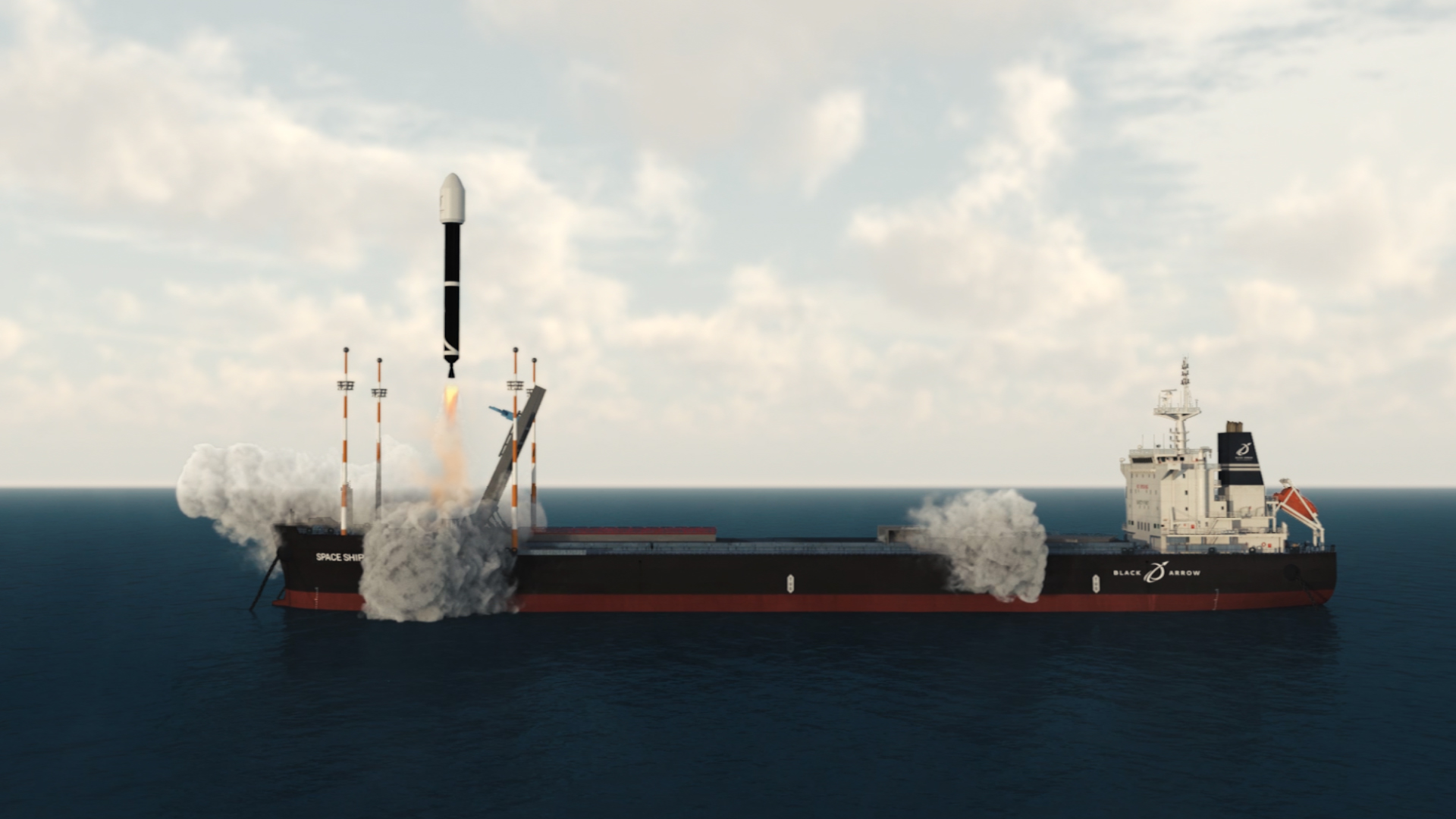 Paul Williams is the Executive Director of the British startup Black Arrow Space Technologies. Black Arrow is developing a sea-borne launch capability based on their current expertise in developing composite propellant tanks for satellites. The launching of rockets from ships has a previous history in America, and as an island nation, the concept is clearly suited for a UK launch provider. Paul and I talk about the heritage of the Black Arrow name, the advantages of a sea-borne launch approach, and the importance of audacious technical challenges in galvanising and inspiring the next generation of engineering talent.
In fact, Black Arrow is currently supporting and working with a number of ambassadors from the Women in Science and Engineering (WISE) campaign. One of these ambassadors is Liv Scott-Golding, a 3rd year Physics undergraduate student at the University of Bristol, who is also joining us on this episode. Liv has been involved with Black Arrow from the start, and with contagious enthusiasm, tells us about her passion for the space industry and her interactions with Black Arrow as a WISE ambassador.
Podcast: Play in new window | Download | Embed
Subscribe: Apple Podcasts | TuneIn | RSS
This episode of the Aerospace Engineering Podcast is brought to you by my patrons on Patreon. Patreon is a way for me to receive regular donations from listeners whenever I release a new episode, and with the help of these generous donors I have been able to pay for much of the expenses, hosting and travels costs that accrue in the production of this podcast. If you would like to support the podcast as a patron, then head over to my Patreon page. There are multiple levels of support, but anything from $1 an episode is highly appreciated. Thank you for your support!
Selected Links from the Episode
 Dr Steve Bullock is an engineering researcher in air-to-air refuelling and cooperative control of UAVs, as well as the Programme Director of the Aerospace Engineering programme at the University of Bristol. As the programme director of a leading European aerospace engineering programme, Steve has a unique vantage point on how the higher education landscape is changing, and specifically, how technology trends such as aviation sustainability and digitisation are changing the requirements for an engineering university education in the 21st century.
As a TeachFirst ambassador and presenter of the Cosmic Shed podcast, Steve has a clear passion for education in general and is actively exploring different ways of disseminating technical information to a broad audience. In this episode of the podcast Steve and I talk about,
- his path into aerospace engineering and how he found his passion for teaching
- his PhD work on air-to-air refuelling and cooperative control
- what he considers to be some of the key challenges in engineering university education
- how the Aerospace Engineering department in Bristol is planning for the future
- and much, much more.
Podcast: Play in new window | Download | Embed
Subscribe: Apple Podcasts | TuneIn | RSS
This episode of the Aerospace Engineering Podcast is brought to you by my patrons on Patreon. Patreon is a way for me to receive regular donations from listeners whenever I release a new episode, and with the help of these generous donors I have been able to pay for much of the expenses, hosting and travels costs that accrue in the production of this podcast. If you would like to support the podcast as a patron, then head over to my Patreon page. There are multiple levels of support, but anything from $1 an episode is highly appreciated. Thank you for your support!
Selected Links from the Episode
 Tom Szirtes is the founder and director of Mbryonic, a London-based digital design studio. Mbryonic specialises in creating virtual reality (VR), augmented reality (AR) and mixed reality (MR) experiences that help organisations communicate, educate and entertain more effectively. Apart from the traditional applications in gaming and education, VR is now increasingly important for industrial design and engineering in general. For example, Mbryonic recently partnered with All Nippon Airways to provide customers an immersive virtual tour of All Nippon’s new business class in the Boeing 777 cabin. Mbryonic has also partnered with Acumen to create ‘The Adient Ascent VR’; a modular aircraft seating system that allows airlines to configure their cabins through a touch screen interface and then experience what it’s actually like to be in the cabin through a VR headset. Apart from discussing these two projects, Tom and I talk about:
- the fundamentals of and differences between virtual reality, augmented reality and mixed reality
- some of the advantages of VR that will transform the aerospace business landscape
- and how engineers can benefit from using the technology
Podcast: Play in new window | Download | Embed
Subscribe: Apple Podcasts | TuneIn | RSS
This episode of the Aerospace Engineering Podcast is brought to you by my patrons on Patreon. Patreon is a way for me to receive regular donations from listeners whenever I release a new episode, and with the help of these generous donors I have been able to pay for much of the expenses, hosting and travels costs that accrue in the production of this podcast. If you would like to support the podcast as a patron, then head over to my Patreon page. There are multiple levels of support, but anything from $1 an episode is highly appreciated. Thank you for your support!
