For aircraft jet propulsion there are in general four distinct designs: the turbojet, turbofan (or bypass engine), turboprop and turboshaft. This post will address the layout and design of the two most common engines used in modern aircraft, the turbojet and turbofan, and explain how their characteristics make each engine applicable for a specific task. Specifically, two important topics are addressed. The first is the multi-shaft engine with separate low-pressure and high-pressure spools and the second is the bypass engine, in which most of the air compressed by a fan bypasses the core combustor and turbine of the engine.
In general each engine is made up of four essential components: the compressor, combustor, turbine and nozzle as shown in Figure 1. The compressor raises the pressure of the incoming air before combustion, and the turbine, which extracts work from the hot pressurised combustion products, are at the heart of the engine. The role of the power turbine is not to provide thrust but to drive the compressor. The hot pressurised combustion products are expanded through a nozzle to produce thrust. In some military turbojet engines the exhaust velocity and therefore the thrust may be increased by “afterburning” in the exhaust duct.
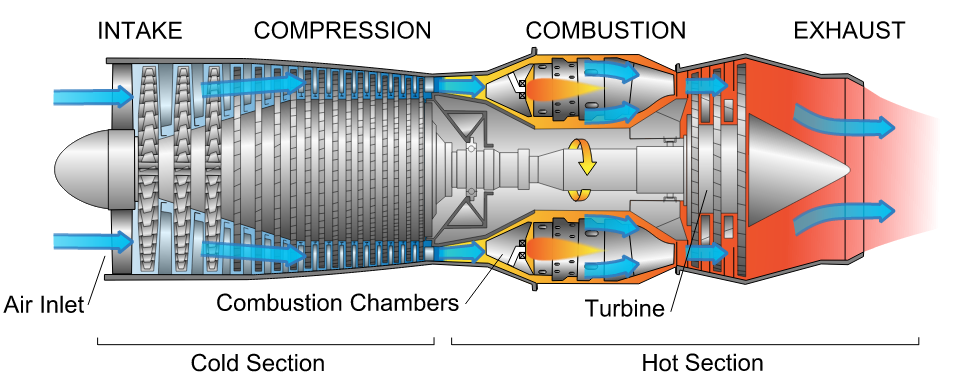
Figure 1. Diagram of a typical gas turbine jet engine. Air is compressed by the fan blades as it enters the engine, and it is mixed and burned with fuel in the combustion section. The hot exhaust gases provide forward thrust and turn the turbines which drive the compressor fan blades. (Photo credit: Wikipedia)
1.1 The Turbojet
The turbojet is the earliest form of the jet engine as developed by Sir Frank Whittle and Hans von Ohain during WWII. It is no longer used for civil aircraft but predominantly used for high-velocity propulsion in military aircraft. Figure 1 shows a cross-sectional drawing of a typical turbojet engine and illustrates the typical layout of a turbojet engine with an axial compressor driven by an axial turbine, all on the same shaft. This assembly of shaft, compressor and turbine is oftentimes referred to as a “spool”. Newer engines typically have two or three spools such that the compression and expansion process in the compressor and turbine are spread over different parts. In this manner a low-pressure (LP) compressor and LP turbine are mounted on one shaft to form the LP spool. The LP shaft passes through the inside of the hollow high-pressure (HP) shaft on which are mounted the HP compressor and HP turbine. The compressor and turbine are split into separate parts to reduce centrifugal stresses in the compressor and turbine blades, and allow different parts of the compressor and turbine to be run at different speeds in order to optimise the running efficiency.
For sustained supersonic speeds a turbojet engine remains and attractive option for aircraft propulsion. The Rolls-Royce Olympus 593 is a two-shaft example that was used to propel the Concorde to twice the speed of sound.
1.2 A Note on Efficiency:
The propulsive or Froude efficiency 


Where 


So that,

For a fixed airspeed 
1.3 Optimisation of the Turbojet
When optimising the jet engine performance two parameters are typically considered: the specific thrust (ST) of the engine, and specific fuel consumption (SFC), the mass flow rate of fuel required to produce a unit of thrust. Generally speaking turbine designer have two thermodynamic variables to optimise these two entities: the compressor pressure ratio (R) and the turbine inlet temperature (TET). The effects of these two variables on SFC and ST will be considered in turn.
ST is strongly dependent on TET and TET should be maximised in order to keep the engine as small as possible for a specific amount of thrust. However, an increase in TET will incur a larger SFC at a constant R. On the other hand a gain in ST is generally more important than the penalty of higher SFC, especially at high flight speeds where a small engine is critical to minimise weight and drag.
Increasing R always causes a reduction in SFC and hence ensuring efficient compression stages is critical for an economic engine. For a fixed value of TET increasing R will initially result in more ST but will eventually cause ST to decrease again. Thus, there exists an optimum value of R, which is the role of the engineer to ascertain. Furthermore, the optimum pressure ratio for maximum ST increases with increasing TET.
This optimisation of R and TET can of course not be separated from the mechanical design of the engine. Driving up TET requires the use of much more expensive alloys and cooled turbine blades, which invariably lead to an increase in cost, mechanical complexity or otherwise a reduction in engine life. Increasing R will require larger compressors and turbines that incur weight, cost and mechanical complexity penalties.
Finally for different flight speeds and flight altitudes the performance of the turbojet will vary since the mass flow rate and momentum drag vary with density of the air and forward speed. Gross thrust decreases considerably with increasing altitude due to the decreasing ambient density and pressure, but specific thrust may increase due to a lower engine intake temperature. SFC however is reduced for increasing altitude, a result that was calculated by Frank Whittle as an engineering student, and led to his motivation for developing the jet engine.
2.1 The Turbofan
As revealed above the high exit velocity of turbojet engines does not allow high propulsive efficiencies required for civil aircraft. To raise the propulsive efficiency a bypass engine, often known as a turbofan engine, is used.
The core of the turbofan engine is essentially the same as the turbojet featuring a compressor, combustion chamber and power turbine as shown in Figure 2. However the engine features a second turbine that drives a large fan at the front of the engine. This fan delivers air to a bypass duct that channels air to the exhaust nozzle without passing through a combustion chamber. For this reason designers often refer to the cold flow in the bypass duct and hot flow through the core. Mixing the colder bypass air with the hot exhaust gases from the core results in higher propulsive efficiencies and lower noise levels. Early bypass engines typically had bypass ratios (the mass flow rate of bypass air divided by the mass flow rate of air going through the core) of around 0.3 to 1.5. The arrangements for modern airliners are High-Bypass-Ratio (HBR) engines with a bypass ratio of 5 or even more. In the Rolls Royce RB211 and Trent families the fan is driven at low speed by one turbine, and two internal compressors driven by another two separate turbines to give a triple spool engine.

Figure 2. Schematic Diagram of Turbofan Engine (Photo credit: Wikipedia)
2.2 Optimisation of the Turbofan
For turbofan design engineers have four major variables to consider: the bypass ratio (BR), overall pressure ratio (OR), fan pressure ratio (FR) and TET. Similar to the turbojet high TET is required for increased thrust. As the FR is increased the thrust contributed by the cold flow is increased while that of the hot flow decreases since more power is required to drive the fan. There is an optimum value of FR for which the total thrust 
The propulsive efficiency rises and the SFC falls as BR is increased. For laung-haul subsonic aircraft SFC is important to reduce cost. For these engines BR is typically between 4 and 6 and OP and TET are high. Thrust is more important for military aircraft such that BR is typically reduced to 0.5 to 1. BR significantly affects the engine efficiency, appearance, size and weight of the engine. As the weight of the engine increases less payload can be added to the aircraft such that the airlines revenue falls. Second, increasing the lift produced by the wings to carry bigger engines automatically induces more drag. Finally, for practical reasons BR > 10 are not practical with current technology since it would be necessary to install a gear box between the driving power turbine and fan to allow the turbine to run faster. Such a design would most certainly require considerable development time and would probably incur a weight penalty that outweighs the benefits of increasing the BR. Thus optimisation of the engine cannot only be considered in terms of thermodynamic parameters and aircraft manufacturers ultimately decide which engine to install based on what design gives airlines the highest financial yield.
Key References
Rolls-Royce (1996). The Jet Engine. Rolls Royce Technical Publications; 5th ed. edition

Reading stories on UFO fluxliner is this really something that’s true
I am not an engineer but I do have a desire to design things. Including “jet engines” which I don’t think are meeting their full potential. Making this statement should make anyone with a real education in aeronautical engineering laugh till their sides hurt. Having a great imagination and always wanting to improve on things I’m reminded of my days of working on Phantom F4’s. I do have an idea for a different approach to engine design but lack the means to test this theory.
Who can I get in touch with to possibly do a computer model and test this idea of money?
Sincerely,
John S. mayes
i am cureious who to talk to about my idea about putting a jet engine inside a car to make it fly it would be a specific jet engine it would have to be small an modified to fit into a specific vehicle dont know were to start?
how about talk to me
facebook.com/guysitshotz
Did you build this yet?
[…] and reliable operation of these engines. The harmonious collaboration between the intricacies of jet engine design and the precise properties of jet fuel propels aviation into new frontiers of performance and fuel […]