A very important parameter when designing jet engines is specific power – the amount of power output divided by the mass of the engine. In general, a good heuristic to keep in mind when designing anything that moves is that maximising the power output per unit mass leads to a more efficient design. Afterburning is an exception to this rule. Yes, afterburning provides more thrust and therefore provides more bang for every gram of jet engine, but it is terribly fuel inefficient.
Afterburning, sometimes also called reheat, is a means of increasing the thrust of a jet engine in order to improve aircraft take-off and climb performance, to accelerate beyond the sound barrier, or in a military setting, for improved combat performance. Of course, we could simply increase the thrust by building a bigger and more powerful engine, but this naturally leads to a greater frontal area that impedes the oncoming flow, and therefore increases drag. Even though afterburning is incredibly fuel-inefficient, it is the best solution for enabling massive amounts of additional thrust at the switch of a button. This means an engine can be run in two modes – a fuel efficient, low thrust configuration and a fuel-inefficient, high-thrust configuration.
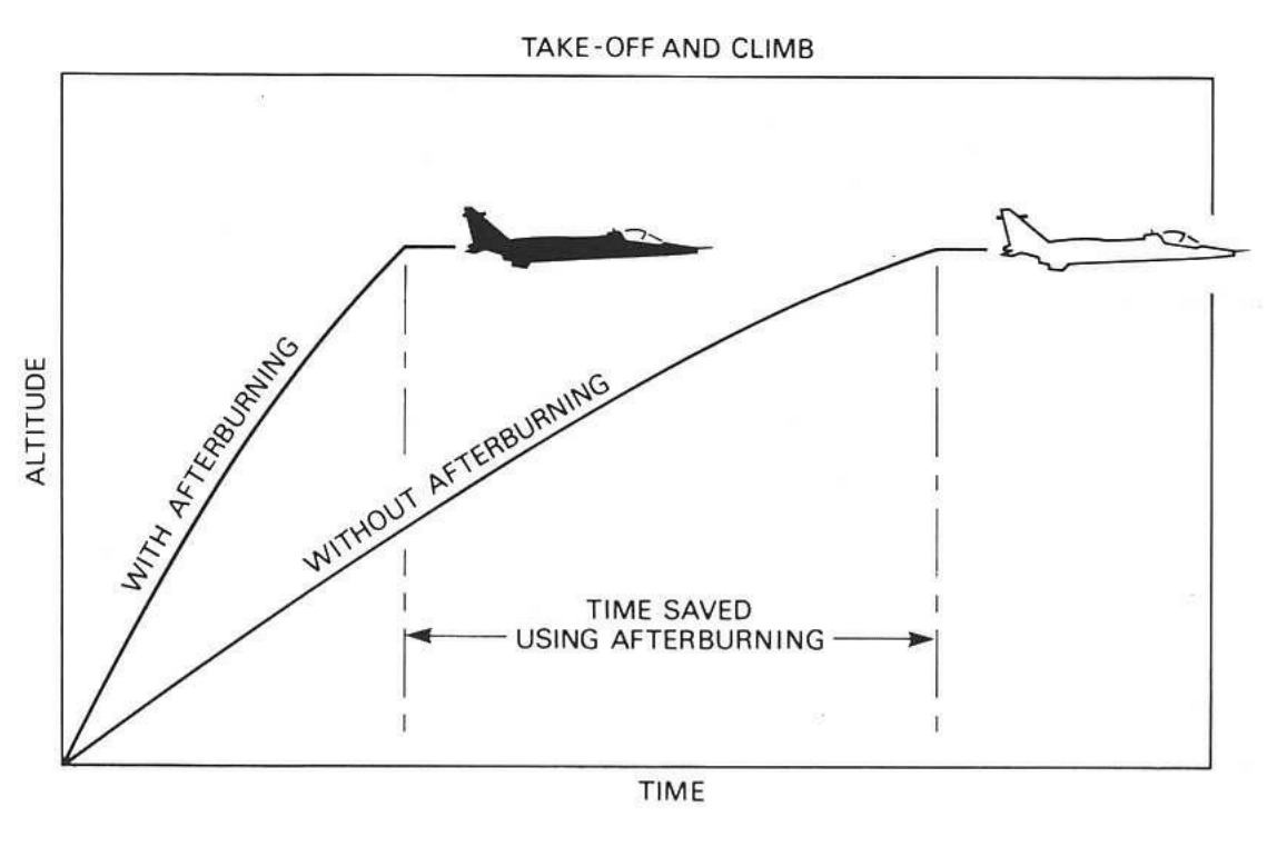
Effect of afterburning during take-off and climbing [1]
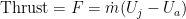
 , and the difference between the entry and exit velocities of air into,
  , and out of,
  , the jet engine.
For a fixed airspeed 

and the rate of change in kinetic energy is
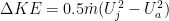
such that the propulsive efficiency is

This means that for a fixed airspeed
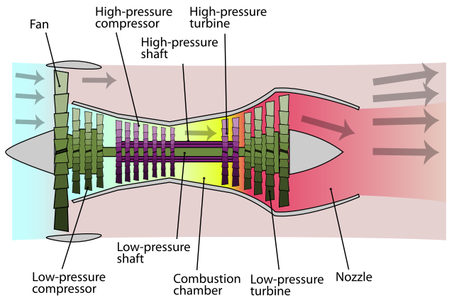
Schematic Diagram of Turbofan Engine (Photo credit: Wikipedia)
High bypass-ratio turbofan engines, which are the most common in modern airliners, are designed around this second principle – the big fan at the front sucks in tons of air, but because this flow bypasses the combustion chamber, it is not accelerated to a high exit velocity. The advantages of this design is that increasing the bypass ratio yields better fuel efficiency which means that turbofans can be operated over long periods (great for long-haul commercial passenger flights).
The downside, of course, is increased size and induced drag, which is a nightmare for nimble fighter aircraft. In fighter aircraft you want a small and compact engine that provides tons of thrust. Fuel efficiency is typically of secondary concern. Therefore, an afterburner naturally addresses the first principle we discussed above – accelerating the exhaust gases to higher velocity. This generally means that we can shrink the size of the engine and decrease the bypass ratio to provide better aerodynamic performance.
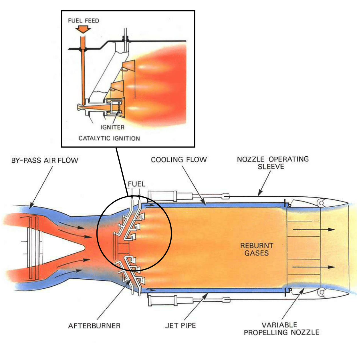
Schematic of afterburning components and functionality at the tail end of a jet engine [1]
The hot jet from the turbine flows into the jet pipe at a velocity of around 250 m/s to 400 m/s, and this velocity is far too high to guarantee stable combustion in the jet pipe. Just prior to the jet pipe, the cross-sectional area of the exit portion to the turbine increases to diffuse the flow to lower velocities. However, because the standard injection rate of kerosene at a good fuel-to-oxygen mixture is only around 1-2 m/s, the kerosene would be rapidly blown away even by the diffused jet stream. To prevent this a vapour gutter is placed just prior to the fuel injection nozzles that spins the jet into turbulent eddie currents, thereby further slowing down the hot turbine exhaust gases and allowing for a better mixture of fuel and jet stream. A common misconception is that due to the high temperature of the gases exiting the turbine (around 700°C), the fuel-oxygen mixture in the jet pipe would combust spontaneously. Cooler combustion flames can develop at these temperatures, but because of the atmospheric pressure differences between ground level and altitude, a design that spontaneously combusts at ground level would never do so at altitude. To guarantee a stable and smooth reaction over a wide range of mixture ratios and flying altitudes, a high-intensity spark is needed.
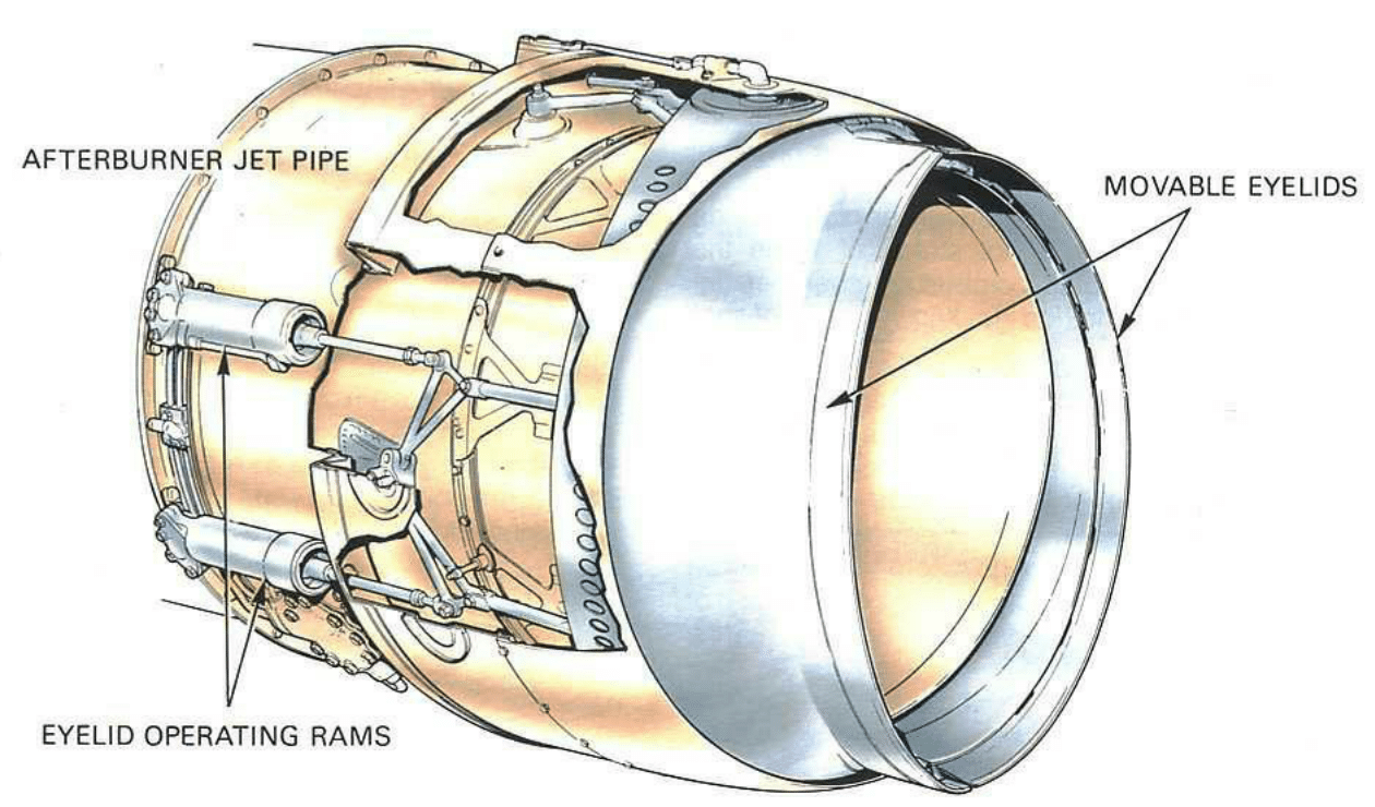
Two-position nozzle [1]
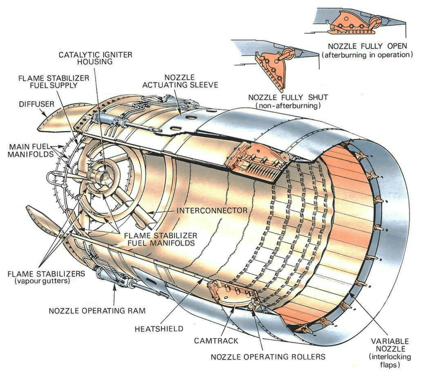
Variable-area nozzle [1]
Thrust and fuel consumption
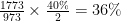
The increase in thrust is a function of the increase in jet pipe temperature as a result of afterburning. For a perfectly efficient system, the relationship between the temperature ratio before and after fuel is burnt, and the thrust increase is nearly linear in the typical operating range with temperature ratios of 1.4 to 2.2. Within this range we can expect a 40% increase in thrust for a doubling of the temperature in the jet pipe. Thus, if afterburning raises the jet pipe temperature from 700°C (973 K) to 1500°C (1773 K) this results in a thrust increase of around 36%.
In a static test bed, thrust increases of up to 70% can be obtained at the top end, and at high forward speeds, several times this can be achieved. The lower the temperature exiting the turbine and the greater the extent of uncombusted oxygen, the greater the temperature increase in the jet pipe due to afterburning.
As is to be expected, afterburning naturally incurs a fuel consumption penalty, and this is why afterburning is typically constrained to short bursts. The aim of the compressor in a classic jet engine is to raise the pressure of the incoming air to the optimal pressure for efficient combustion. After expansion by the turbine stage, the gases are at a lower degree of compression, and therefore the fuel is not burnt as efficiently as in the combustion chamber between compressor and turbine. For a 70% increase in thrust the fuel consumption can easily double, but of course this increased fuel consumption is balanced by an improved performance in terms of take-off and climb. This means that the increased fuel consumption is balanced by the time saved to cover a desired distance or operating manoeuvre.
If you are interested in jet engine design, check out my posts on its history, compressor and turbine design, jet engine optimisation and turbine cooling.
References
The inspiration of this post and the diagrams have all been taken or inspired by [1] Rolls-Royce (1996). The Jet Engine. Rolls Royce Technical Publications; 5th ed. edition (Amazon link). For anyone interested in jet engine design this is a beautiful book, describing lots of intricate details about jet engine design and presenting the information in an intuitive and visually pleasing manner using diagrams as used throughout this post. I can not recommend this book enough.

Very informative article, loved it !