How airplanes fly is one of the most fundamental questions in aerospace engineering. Given its importance to flight, it is surprising how many different and oftentimes wrong explanations are being perpetuated online and in textbooks. Just throughout my time in school and university, I have been confronted with several different explanations of how wings create lift.
Most importantly, the equal transit time theory, explained further below, is taught in many school textbooks and therefore instils faulty intuitions about lift very early on. This is not necessarily because more advanced theories are harder to understand or require a lot maths. In fact, the theory that requires the simplest assumptions and least abstraction is typically considered to be the most useful.
In science, the simplicity of a theory is a hallmark of its elegance. According to Einstein (or Louis Zukofsky or Roger Sessions or William of Ockham…I give up, who knows), “everything should be made as simple as possible, but not simpler.” Hence, the strength of a theory is related to:
- The simplicity of its assumptions, ideally as few as possible.
- The diversity of phenomena the theory can explain, including phenomena that other theories could not explain.
Keeping this definition in mind, let’s investigate some popular theories about how aircraft create lift.
The first explanation of lift that I came across as a middle school student was the theory of “Equal Transit Times”. This theory assumes that the individual packets of air flowing across the top and bottom surfaces must reach the trailing edge of the airfoil at the same time. For this to occur, the airflow over the longer top surface must be travelling faster than the air flowing over the bottom surface. Bernoulli’s principle, i.e. along a streamline an increasing pressure gradient causes the flow speed to decrease and vice versa, is then invoked to deduce that the speed differential creates a pressure differential between the top and bottom surfaces, which invariably pushes the wing up. This explanation has a number of fallacies:
- There is no physical law that requires equal transit times, i.e. the underlying assumptions are certainly not as simple as possible.
- It fails to explain why aircraft can fly upside down, i.e. does not explain all phenomena.
As this video shows, the air over the top surface does indeed flow faster than on the bottom surface, but the flows certainly do not reach the trailing edge at the same time. Hence, this theory of equal transit times is often referred to as the “Equal Transit Time Fallacy”.
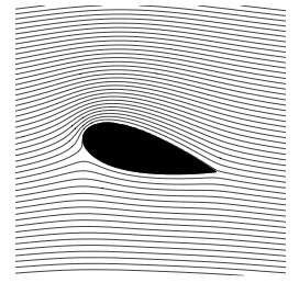
In order to generalise the above theory, while maintaining the mathematical relationship between speed and pressure given by Bernoulli’s principle, we can relax the initial assumption of equal transit time. If we start from a phenomenological observation of streamlines around an airfoil, as depicted schematically below, we see can see that the streamlines are bunched together towards the top surface of the leading edge, and spread apart towards the bottom surface of the leading edge. The flow between two adjacent streamlines is often called a streamtube, and the upper and lower streamtubes are highlighted in shades of blue in the figure below. The definition of a streamline is the line a fluid particle would traverse as it flows through space, and thus, by definition, fluid can never cross a streamline. As two adjacent streamlines form the boundaries of the streamtubes, the mass flow rate through each streamtube must be conserved, i.e. no fluid enters from the outside, and no fluid particles are created or destroyed. To conserve the mass flow rate in the upper streamline as it becomes narrower, the fluid must flow faster. Similarly, to conserve the mass flow rate in the lower streamtube as it widens, the fluid must slow down. Hence, in accordance with the speed-pressure relationship of Bernoulli’s principle, this constriction of the streamtubes means that we have a net pressure differential that generates a lift force.

Flow lines around a NACA 0012 airfoil at 11° angle of attack, with upper and lower streamtubes identified.
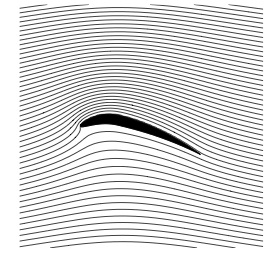
Of course, this theory does not explain why the upper streamtube contracts and the lower streamtube expands in the first place. An intuitive explanation for this involves the argument that the angle of attack obstructs the flow more towards the bottom of the airfoil than towards the top. However, this does not explain how asymmetric airfoils with pronounced positive camber at zero angle of attack, as shown in the figure below, create lift. In fact, such profiles were successfully used on early aircraft due to their resemblance to bird wings. Again, this theory does not explain all the physical phenomena we would like it to explain, and is therefore not the rigorous theory we are looking for.

Asymmetric airfoil with pronounced camber [1]
Indeed, we can imagine a flow around a 2D cylinder shown in the figure below. The flow is symmetric from left-to-right and top-to-bottom and experiences no lift. If we now start the cylinder spinning at the rate 
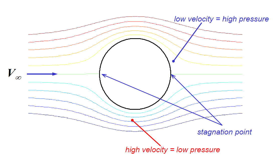
Flow around a cylinder
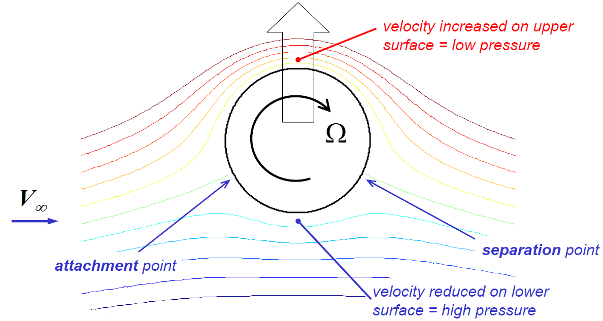
Flow around a rotating cylinder that induces lift
In the example above, lift was induced by creating an asymmetry in the curvature of the streamlines. In the stationary cylinder we had streamlines curving in one direction on the top surface, and by the same amount in the opposite direction on the bottom surface. Rotating the cylinder created an asymmetry in streamline curvature between the top and bottom surfaces (more curvature upwards then curvature downwards). We can create a similar asymmetry in the flow with a stationary cylinder by placing a small sharp-edged flap at the rear edge and positioned slightly downwards. Real viscous flow might not necessarily flow as smoothly around the little flap as shown in the diagram below, but this mental model is a neat tool to imagine how we can morphologically transition from a rotating cylinder that produces lift to an airfoil. This is shown via the series of diagrams below. This series of pictures shows that an airfoil creates a smoother variation in velocity than the cylinder, which leads to a smaller chance of boundary layer separation (a source of drag and in the worst-case scenario aerodynamic stall). A similar streamline profile could also be created with a symmetric airfoil that introduces asymmetry into the flow by being positioned at a positive angle of attack.
![]()
![]()
![]()
![]()
The reason why differences in streamline curvature induce lift is addressed in a journal paper by Dr Holger Babinsky, which is free to download. If we consider purely stead-state flow and neglect the effects of gravity, surface tension and friction we can derive some very basic, yet insightful, equations that explain the induced pressure difference. Quite intuitively this argument shows that a force acting parallel to a streamline causes the flow to accelerate or decelerate along its tangential path, whereas a force acting perpendicular to the flow direction causes the streamline to curve.
The first case is described mathematically by Bernoulli’s principle and depicted in the figure below. If we imagine a small fluid particle of finite length l situated in a field of varying pressure, then the front and back surfaces of the particle will experience different pressures. Say the pressure increases along the streamline, then the force acting on the front face pointing in the direction of motion is greater than the force acting on the rear surface. Hence, according to Newton’s second law, this increasing pressure field along the streamline causes the flow speed to decrease and vice versa. However, this approach is valid only along a single streamline. Bernoulli’s principle can not be used to relate the speed and pressures of adjacent streamlines. Thus, we can not use Bernoulli’s principle to compare the flows on the bottom and top surfaces of an airfoil, and therefore can say little about their relative pressures and speeds.
![Flow along a straight streamline [2]](https://aerospaceengineeringblog.com/wp-content/uploads/2015/10/Untitled.jpg)
Flow along a straight streamline [2]
![Flow along a curved streamline [2]](https://aerospaceengineeringblog.com/wp-content/uploads/2015/10/Untitled1.jpg)
Flow along a curved streamline [2]

where R is the radius of curvature of the flow and 
One positive characteristic of this theory is that it explains other phenomena outside our interest in airfoils. Vortices, such as tornados, consist of concentric circles of streamlines, which suggests that the pressure decreases as we move from the outside to the core of the vortex. This observation agrees with our intuitive understanding of tornados sucking objects into the sky.
With this understanding we can now return to the study of airfoils. Consider the simple flow path along a curved plate shown in the figure below. At point A the flow field is unperturbed by the presence of the airflow and the local pressure is equal to the atmospheric pressure 


![Flow around a curved airfoil [2]](https://aerospaceengineeringblog.com/wp-content/uploads/2015/10/Untitled2.jpg)
Flow around a curved airfoil [2]
A couple of interesting observations follow from the above discussion. Nature typically uses thin wings with high camber, whereas man-made flying machines typically have thicker airfoils due to their improved structural performance, i.e. stiffness. In the figure below, the deep camber thinner wing shows highly curved flow in the same direction on both the top and bottom surfaces.
Deep camber thin wing with high lift [2]
Shallow camber thick wing with less lift [2]
The more shallow camber thicker wing has flow curved in two different directions on the bottom surface and will therefore result in less pressure difference between the top and bottom surfaces. Thus, for maximum lift, the thin, deeply cambered airfoils used by birds are the optimum configuration.
In conclusion, we have investigated a number of different theories explaining how lift is created around airfoils. Each theory was investigated in terms of the simplicity and validity of its underlying assumptions, and the diversity of phenomena it can describe. The theories based on Bernoulli’s principle, such as the equal transit time theory and the contraction of streamtubes theory, were either based on faulty initial assumptions, i.e. equal time, or failed to explain why streamtubes should contract or expand in the first place. The theory based on airfoils deflecting airflow downwards is theoretically accurate and correct (Newton’s third law: changes in fluid momentum over a control volume including the airfoil lead to a reactive lift force), but by being an integral approach it is not helpful in explaining what occurs between the leading and trailing edges of the airfoil (e.g. upwash is also a contributing factor to lift).
A more intricate theory is that curved bodies induce curved streamlines, as the inherent viscosity of the fluid forces the fluid to adhere to the surface of the body via a boundary layer. The centripetal forces that arise in the curved flow lead to a drop in pressure across the streamlines towards the centre of curvature. This means that if a body leads to asymmetric curved streamlines across it, then the induced pressure differential arising from the asymmetry induces a net lift force.
Edits and Acknowledgments
A previous version of this article referenced a misleading and incorrect example of a highly cambered airfoil as a counterexample to the theory of airfoils deflecting airflow downwards and the theoretical explanation using control volumes. Dr Thomas Albrecht of Monash University pointed this error out to me (see the discussion in the comments) and his contribution in improving the article is gratefully acknowledged.
Photo credit
[1] DThanhvp. Photobucket. http://s37.photobucket.com/user/DThanhvp/media/American.jpg.html
[2] Babinsky, H. (2003). How do wings work?. Physics Education 38(6) pp. 497-503. URL: http://iopscience.iop.org/article/10.1088/0031-9120/38/6/001/pdf;jsessionid=64686DBCB81FEB401CFFB87E18DFE6DA.c1

Hi
I enjoy your newsletters. They relate information in terms which can be understood by those other than engineers. Please check out my blog to see why I am interested in aerospace.
Keep up the good work.
DJH
Hi David, thanks for reading. I’ll check out your blog.
Informative blog. Thank you for sharing.
Overall an interesting read, but the section in which you try to disprove the application of Newton’s third law is, well, plain wrong. Are you really suggesting that Newton’s third law, and conservation of momentum, holds everywhere in classical mechanics, except for aerodynamics? Please correct this, it adds to the confusion as to how lift is generated, and discredits you as an aerospace engineer.
You base your argument on the “counterexample” given in the figure “high camber airfoil with control volume”. But just because you draw parallel flow into and out of a control volume and then claim this would still produce lift, doesn’t mean that this is in fact what happens in nature. I invite you to produce a proper reference — all lift-producing flows I have seen in 15 years working in numerical and experimental aerodynamics _do_ obey Newton’s third law, ie. would have non-parallel in- and outflow of a control volume this close to the wing.
Also, angle of attack is defined as the angle between free-stream velocity and the chord line. Free-stream velocity is the one very far away from the wing. In your figure, AoA is clearly non-zero (ie, the camber line is not horizontal).
Finally, aircraft designers usually want a _low_ stall speed — we don’t want to approach the ground at 300 KIAS. That is, the benefit of cambered wings is that they _decrease_ the stall speed.
Hi Thomas, thank for your thoughtful comment. I am obviously not suggesting that Newton’s third law does not hold in aerodynamics. In fact, if you consider the curved streamline explanation later, I say that there is a continuous change of the streamline vector over the two surfaces, which necessitates the centrifugal-centripetal action-reaction pair of Newton’s third law. But on reading the “counter-example” section again, I have to agree with you that I did not express myself clearly enough and that the example of the highly cambered wing is misleading and incorrect. With the highly cambered wing I was trying to address the claim that an airfoil works simply by pushing air downwards, and as a reaction, the airfoil therefore experiences lift. So we draw a control volume around the airfoil, observe a net change in momentum in the vertical plane between the beginning and end of the control volume, and hence the airfoil encounters lift. I don’t think I said anywhere that Newton’s third law is invalid but that the explanation of pushing air downwards is too simplistic (at least that is what I meant to say). The point I was trying to make is that the “net pushing air down” approach neglects what happens along the way over the airfoil surface between the leading and trailing edges, and it also does not address the question how much the flow is actually deflected by. I have now included a new example of a rotating cylinder and a clearer explanation of what I meant. Thanks for pointing out the flaws in my thinking on this topic and let me know if you see anything wrong with the new example. Thanks, Rainer
Hi Rainer,
I appreciate the effort you’re putting into this! Some more comments:
OK, we seem to agree that explanation of pushing air downwards is correct. The control volume explanation is an integral approach; as such it doesn’t neglect anything. Quite the opposite, it includes the effect even the smallest details have on the overall lift, it just doesn’t explain _how_ they do it. Not sure if I would call it “too simplistic”, but that might be just due to my non-English speaking background.
I agree with the first two figures in your new example (except that “separation” and “attachment” points are typically used with separation bubbles; the two points in your example are still stagnation points), but I don’t think that the third figure is a particularly good example. The flow must be extremely viscous to not separate and follow the curvature of the upper half of the cylinder. Such creeping flow is far from any practical application; also, if the flow is that viscous, it would probably creep around the sharp flap, as well. For practical Reynolds numbers OTOH, the boundary layer would just separate once the pressure increases after the widest part of the cylinder, leaving the flap in the dead water zone basically ineffective. If fixing the trailing stagnation point to an arbitrary location was that simple, aircraft wings wouldn’t need such complicated three- or four element flaps for the low-speed/high c_A regime. I suggest to remove the third figure; the second already supports the point that you need curved streamlines and asymmetry.
Upon reading this again: “With the highly cambered wing I was trying to address the claim that an airfoil works simply by pushing air downwards, and as a reaction, the airfoil therefore experiences lift”, let me hammer this home: it’s not a claim, it’s a fact. Whenever you see something flowing into a control volume at one angle and leaving the CV at another angle, whatever happened inside the CV has produced lift. Again, it doesn’t explain how, but it does tell you how much.
Hi Thomas, thanks for your additional comments. I will have to concede that the third picture was not very realistic. It was supposed to be an illustration and perhaps a hint at how we can undergo a morphological transition from a rotating cylinder to a stationary airfoil by successively increasing the length of the little flap. As you point out the little flap would certainly not have the effect I showed under real conditions but as we start increasing its length and morph towards an airfoil shape the boundary layer separation you describe would decrease. In that sense I think the flap diagram helps to bridge the gap of how we go from breaking the symmetry using rotation to breaking it through geometry. I have removed the figure for now but if you agree with this “mind experiment” I may add another version that includes this morphological transition to an airfoil through a series of steps? What do you think?
Yes, I certainly agree with you hammering home the point about change in flow angle = change in momentum = lift. I am not going to argue about a fundamental law of physics. But I am nevertheless curious about where you then go about constructing the control volumes. If we have a long, very thin plate which is parallel to a flow with a little upwards bend in the middle (say 1/3 length straight, then 1/3 half-cylinder, 1/3 straight again) this profile would create lift. Yet, if I draw a control volume over the entire plate I can pretty much draw straight streamlines in and out. I guess this means we need to construct the control volume over the half-cylinder portion of this plate only? Or I am I applying the notion of control volumes in aerodynamics incorrectly?
Hi Rainer,
First, I should probably apologise for my German bluntness in the first response. Reading it again, I can imagine it sounds quite rude.
Interesting thought about the flat plate/half-cylinder airfoil. I’m inclined to compute both viscous and inviscid flow around such a geometry, and see what happens. Might take a while though until I find the time to do so. If it does create lift, my intuition says that streamlines upstream of the leading edge would approach that leading edge from below, similar to what is shown in figure “Deep camber thin wing with high lift”, just because lift is proportional to circulation.
Also, think of how such an airfoil would be modeled using thin airfoil theory: you’d place a potential vortex sheet at the chord line, compute the vortex distribution such that no flow crosses the airfoil, and apply the Kutta condition to fix the aft stagnation point to the trailing edge. The vortex sheet induces circulation everywhere, and again I can imagine the streamlines upstream of the leading edge would point upwards. I should really calculate this!
Another aspect we shouldn’t forget: To get proper lift from the CV approach, you integrate over it’s _entire_ surface, i.e. not just the inflow/outflow, but also the top and bottom. Above the curved part of the airfoil, streamlines will be curved outwards, whereas they will be curved inwards below it. This breaks symmetry, which the CV approach ‘feels’ via its top and bottom surfaces.
Good point about the transition from a rotating cylinder to an airfoil (without forcing the reader through conformal maps and Joukowski transform). I guess if you just make the cylinder more like a very thick airfoil, i.e. keep the leading edge radius, but extend the cylinder along the trailing stagnation streamline for, say, one radius, it could work.
Hi Thomas,
thanks again for your detailed comments. Nevermind your first comment, it wasn’t rude. German interlude: Ich bin auch Deutscher und bin den direkten Umgang unserer Wissenschaftskultur gewohnt :). To be honest, I am really grateful for your suggestions and corrections. This site is not only about me trying to pass on what I have learned but also to further my personal education about certain intricacies of aerospace engineering. So thanks for your input!
I might try and come up with some figures that capture the transition from cylinder to airfoil. As you say, I visual approach is often more intuitive than forcing the reader through formal mathematics.
I see your point about the streamlines ahead of the leading edge. I can imagine that purely from a continuity requirement (downstream being linked to upstream) the streamlines may need to approach from below. Although I like your comment about the top and bottom surfaces of the CV best. I had completely ignored that. Of course we need to include the entire surface and not just the left and right sides, and the top and bottom will definitely “see” the asymmetry in the flow. That’s really nice, thanks for that!
I think your explanation is great. Now could you explain how a lift type vertical wind turbine spins? Since the AOA is constantly changing because the wings are spinning.
Also the wings on a darrieus VAWT are symmetrical. Be as simpkle as you can.
Hi Rainer,
Your blog was referenced in a You Tube comment.
I’m a very experienced electrical engineer, mentor and county college teacher. I also do STEM demos and lectures for local primary schools and scouts and volunteer at a local challenger center. https://www.challenger.org/ [not all at once]
.
I take my knowledge and teaching very seriously and have had, from a very early age, a deep desire to understand thing in the most fundamental way. My professional career, 36+ years at Motorola was successful because of my knowledge fueled by this desire.
.
Several years ago I assumed responsibility for a very sophisticated full cockpit B-737 flight simulator that was custom constructed for and donated to the center by owners of a local aircraft controls company, now owned by Woodward.
.
Having heard the Equal Transit/longer Path fallacy in early pilot training many years ago, but not thinking about it then, I decided to ‘brush up’ on things I may be asked about regarding the simulator, with lift being one.
.
I was and still am frustrated by all the well-meaning, but obviously problematic explanations easily available on the web and went to more serious research of the well-known authors and have even discussed things with some big names to make sure I have things correct. I also found that they even have trouble putting things into non-engineering language since they are so deeply invested in all the advanced concepts – which are not really necessary to understand the fundamental concepts of lift. After comparing their writings I came to the conclusion that in some places where they seem to differ, it is a matter of semantics rather than actual concepts.
I’ve also had numerous discussions with my Aeronautical Engineer son which also helped greatly to ‘keep me honest’
.
I see so many people struggling with this, so over the last several years I’ve pieced an explanation together. To get right to the meat of the subject, I put any discussions about common fallacies at the end.
.
It is a step-by-step physics of lift while maintaining a solid basis on the applicable, well-known fundamentals of physics/science.
You can read my paper here: https://rxesywwbdscllwpn.quora.com/
..
You clearly gave this serious thought and you may make comments. I can use them to improve it.
Regards, Steve
.
P.S. I have no problem discussing this un a direct, engineering-like (and possibly German) manner.(;-o) (My wife is German-born)
Hi Steve, thanks for your comment. I will have a look at your paper, but at a first glance it definitely looks and reads like you have given the origins of lift plenty of thought and tried to boil the phenomenon down to fundamental physics that can be easily understood. Very commendable effort, and this was precisely my motivation behind this blog post 🙂
Thanks,
Rainer
[…] worry; it is not rocket science. Just look at how birds’ wings or airplanes work. The process of hydrofoil surfing is almost similar. When you attach the hydrofoil under the board, […]
[…] What Creates Lift – How Do Wings Work? – Aerospace … […]
“This net centripetal force must be caused by a pressure differential on either side of the particle as we have ignored the influence of gravity and friction.” I might be dumb and missed this, but why is there there a pressure differential? Is it because the particle is decreasing it’s velocity in the Y direction as it moved along the curved streamline and therefore pressure must increase?
Hi Patrick, thanks for your question. A particle moving along a curved streamline is constantly accelerating (changing its velocity) because the direction of motion is changing (velocity is a vector, i.e. speed plus a direction). By Newton’s second law, acceleration can only happen under a net force. Here, this force is a centripetal force just like what we feel when driving around a corner, i.e perpendicular to the streamline. In a fluid, this net centripetal force must come from a pressure differential across the particle (i.e. perpendicular to the flow direction in the direction of the centripetal force) because nothing else can be pushing on the particle (ignoring gravity and shear friction). Hope this makes it clearer.
Yeah I gotcha. I guess I was looking for what causes the pressure differential rather than there exists a force and noting else could cause it. But if it’s just a fact then I’ll take it.
Also, are these concepts the same for hydrofoils?
Questions for the “Aero experts” herein: 1) I used to sail small sail boats, 20′-24′ long just off LAX wherein 747-400 jets, weighing approx 910,00 lbs or so & other large airplanes would land & pass not more than ~50-100 feet overhead with full flaps extended. We/I never experienced as much as a single ripple of a breeze from this event. 2) On the internet I recently saw where 20 or so cadets in full dress uniform & hats would line up on a runway & the Thunderbird jets would pass not 50 feet over head; they did not experience a ripple of “downwash” & their hats did not budge an inch. Q. Where is the “downwash” you claim from said Lift Force?
Hi, thanks for your question. There is no global downwash. The air passing underneath the airfoil is also moving at relatively high speed horizontally and you can almost imagine this as a barrier against the airflow on the top surface. Indeed you can see this in the streamlines drawn around the rotating cylinder in the post. However, it is even clearer in this video (https://www.youtube.com/watch?v=UqBmdZ-BNig). If you look back at the post, the upwash to the front and downwash aft are used locally to compare the relative flow at the leading edge to the flow at the trailing edge of the cylinder. Not as a global descriptor of downwash.
So, Rainer & other experts: if this airfoil was located inside a wind tunnel, would you claim that the top & bottom walls of said wind tunnel would not experience a mating matching force since “there is no global downwash”?